Dell PowerEdge 6300 and 4300 Systems 1 x 2 Backplane Installation Information3
,QVWDOOLQJWKH'ULYH&DJH
To install the drive cage, perform the following steps:
1. Ensure that the drive cage is correctly assembled:
a. Verify that the 1 x 2 backplane is connected to the edge of the auxiliary SCSI
backplane via a 100-pin connector.
b. Verify that the auxiliary SCSI backplane is inserted into the enclosure on the
side of the cage and secured with one screw.
c. Verify that the 1 x 2 backplane is secured to the back of the cage with four
screws.
d. Verify that a drive rail is attached to each side of the drive cage.
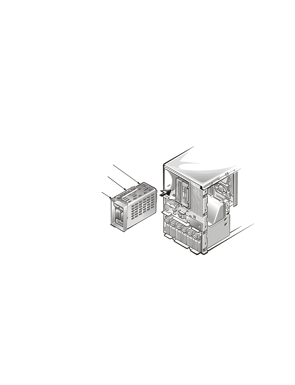
2. Insert the drive cage into the empty peripheral drive bay until the clips on the
drive rails snap into the sides of the peripheral drive bay (see Figure 1).
)LJXUH,QVWDOOLQJWKH'ULYH&DJH
,QVWDOOLQJWKH,
&([WHQVLRQ&DEOH
To in st al l t he I
2
C extension cable, perform the following steps:
1. Disconnect the I
2
C cable from the 20-pin connector on the system board and set
it to one side (see Figure 2).
drive rail
clip
drive cage
