


Dell E176FPc
43
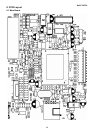
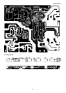
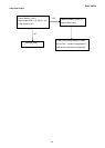
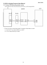
Panel Power Circuit
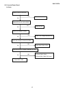
Inverter Control Relative Circuit
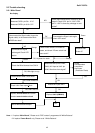
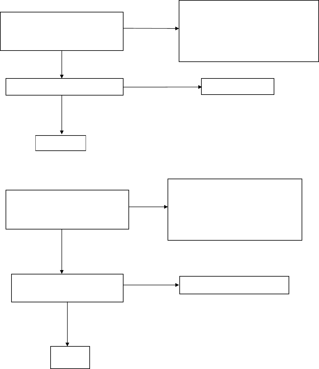
Measured the inverter connector CN402
Pin2 on/off control=3.3V (on)
Pin4 PWM signal control dim 0V-5V
Replace Inverter board to new-one
And check the screen is normal?
OK
Check the BKlt-On relative circuit, R705; in
normal operation, when LED=green, R705
BKlt-On should=3.3V, If BKlt-On no-response
when the power switch turn on-off, Replace
U401
Check NO SCREEN APPEAR block
NG
NG
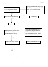
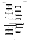
NG, still no screen
Check C101 should have response from
0V to 5V when we switch the power
switch from off to on
Check the PPWR panel power relative circuit,
Q704, Q706; in normal operation, When LED
=green, V-R725 should =5V,If PPWR
no-response when the power switch turn on and
turn off,
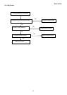
OK
NG
Check CN101, if it is not soldered well Change CN101
Change panel
NG
OK