


Replacing the Mini-Card
1. Remove the new Mini-Card from its packaging.
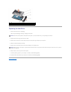
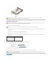
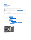
2. Insert the Mini-Card connector at a 45-degree angle into the appropriate system board connector. For example, the WLAN card connector is labeled
WLAN and so on.
3. Press the other end of the Mini-Card down into the slot on the system board.
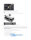
4. Replace the screw that secures the Mini-Card to the system board connector.
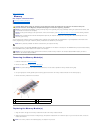
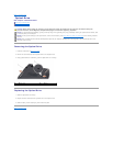
5. Connect the appropriate antenna cables to the Mini-Card. The following table provides the antenna cable color scheme for the Mini-Card supported by
your computer:
6. Replace the following parts based on the display adapter supported by your computer.
l Mobile Intel®GMA:
¡ Replace the base cover (see Replacing the Base Cover).
l ATI Mobility Radeon:
¡ Replace the system board (see Replacing the System Board).
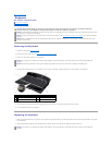
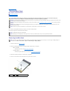
7. Slide the battery into the battery bay until it clicks into place.
8. Install the drivers and utilities for your computer, as required. For more information, see the Dell Technology Guide.
Back to Contents Page
NOTICE: When the Mini-Card is not in the computer, store it in protective antistatic packaging. For more information, see "Protecting Against
Electrostatic Discharge" in the safety information that shipped with your computer.
NOTE: The location of the Mini-Card may change according to the display adapter supported by your computer. To find the type of display adapter on
your computer, click Start® Control Panel® System® Device Manager® Display adapters.
NOTICE: Use firm and even pressure to slide the card into place. If you use excessive force, you may damage the connector.
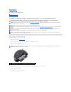
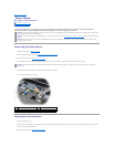
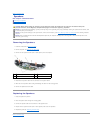
Connectors on the Mini-Card
Antenna Cable Color Scheme
WLAN (2 antenna cables)
Main WLAN (white triangle)
Auxiliary WLAN (black triangle)
white
black
NOTE: If you are installing a communication card from a source other than Dell, you must install the appropriate drivers and utilities. For more generic
driver information, see the Dell Technology Guide.