Quick SAS Cabling Guide
Page 5
Fault-tolerant Asymmetric Cabling Scheme
Although more complex to set up, the fault-tolerant asymmetric cabling scheme is the recommend way of
connecting the expansion enclosures to the RAID array as it makes the enclosure loss protection possible.
Enclosure loss protection is an attribute of a disk group. Enclosure loss protection guarantees accessibility
to the data on the virtual disks in a disk group if a total loss of communication occurs with a single
expansion enclosure. An example of total loss of communication might be loss of power to the expansion
enclosure or failure of both EMM modules. Naturally, the enclosure loss protection is not guaranteed if a
physical disk has already failed in the disk group. In this situation, losing access to an expansion enclosure
and consequently another physical disk in the disk group causes a double physical disk failure and loss of
data.
Enclosure loss protection is achieved when you create a disk group where all of the physical disks that
comprise the disk group are located in different expansion enclosures. This distinction depends on the RAID
level.
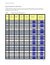
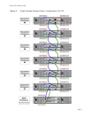
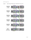
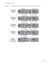
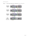
For the diagram illustrating how to cable the specific configuration you have please see
(hyperlink)
Table 1
Note: An incorrect SAS cabling will be detected by the array system. The MD32xx/MD32xxi Storage Manager
will warn you about the mis-wired enclosures by logging a major event in the event log. In addition, the
Recovery Guru will point you to the mis-wire condition and provide you some guidance on correcting the
problem. Please remember that a mis-wire condition will only be reported if incorrectly plugged SAS cables
result in a non-working configuration. In theory, it is possible to attach the expansion enclosures in a
technically correct manner, which will not be optimal but still be functional. The mis-wire events will not
be logged for a configuration of this type.
Simple Cascade Cabling Scheme
The simple cascade cabling scheme could be used when the enclosure loss protection is not required.
The advantage of using this scheme is the simplicity of the initial system set up.
For the diagram illustrating how to cable the specific configuration you have please see
(hyperlink)
Table 1
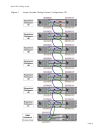
Diagrams
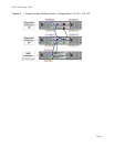
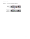
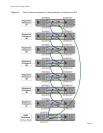
This section contains diagrams illustrating the MD32x/MD32xxi system configurations.
The last diagram
(hyperlink)
Figure 15 contained in this section is a special case: it contains picture of the
labels which you can print, cut out and attach to the both ends of every SAS cable used in your
configuration for an easy identification. If after initial wiring your array system has to be
transported/moved then the labeled SAS cables will simplify the task of re-assembling the system.


