


13 Using MLAG in Dell Networks
.
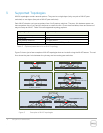
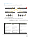
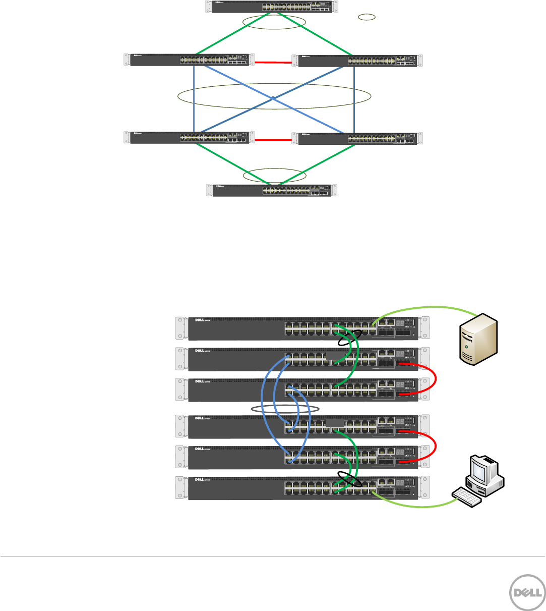
5 Two-Tier Example
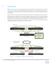
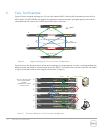
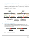
Figure 5 shows a logical topology for a 2-tier fully meshed MLAG, offering full redundancy across all four
MLAG peers. Six Dell N3024s are used for the example, however the same principals apply and the same
commands can be used on the N2000 and N4000 series switches.
2 tier
(2 layer, full mesh)
Peer-Link
= MLAG
Stack No.
1
2
1 2SFP+
3 5 7 9 11
4 6 8 10 12
13 15 17 19 21
14 16 18 20 22 24
LNK ACT
1
2
COMBO P
23
LNK ACT
Stack No.
1
2
1 2SFP+
3 5 7 9 11
4 6 8 10 12
13 15 17 19 21
14 16 18 20 22 24
LNK ACT
1
2
COMBO P
23
LNK ACT
Stack No.
1
2
1 2SFP+
3 5 7 9 11
4 6 8 10 12
13 15 17 19 21
14 16 18 20 22 24
LNK ACT
1
2
COMBO P
23
LNK ACT
Stack No.
1
2
1 2SFP+
3 5 7 9 11
4 6 8 10 12
13 15 17 19 21
14 16 18 20 22 24
LNK ACT
1
2
COMBO P
23
LNK ACT
Stack No.
1
2
1 2SFP+
3 5 7 9 11
4 6 8 10 12
13 15 17 19 21
14 16 18 20 22 24
LNK ACT
1
2
COMBO P
23
LNK ACT
Stack No.
1
2
1 2SFP+
3 5 7 9 11
4 6 8 10 12
13 15 17 19 21
14 16 18 20 22 24
LNK ACT
1
2
COMBO P
23
LNK ACT
A.
B.
E.
D.
C.
F.
Peer-Link
Logical topology of a 2-tier full mesh configuration Figure 5
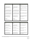
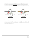
Figure 6 shows the physical layout of the same topology as it might appear in a rack, including cabling and
attached hosts that need to communicate across the MLAG. The same color scheme is used for the cables
in Figure 6 that was used to show logical connections in Figure 5.
Stack No.
1
2
1 2SFP+
3 5 7 9 11
4 6 8 10 12
13 15 17 19 21
14 16 18 20 22 24
LNK ACT
1
2
COMBO P
23
LNK ACT
Stack No.
1
2
1 2SFP+
3 5 7 9 11
4 6 8 10 12
13 15 17 19 21
14 16 18 20 22 24
LNK ACT
1
2
COMBO P
23
LNK ACT
Stack No.
1
2
1 2SFP+
3 5 7 9 11
4 6 8 10 12
13 15 17 19 21
14 16 18 20 22 24
LNK ACT
1
2
COMBO P
23
LNK ACT
Stack No.
1
2
1 2SFP+
3 5 7 9 11
4 6 8 10 12
13 15 17 19 21
14 16 18 20 22 24
LNK ACT
1
2
COMBO P
23
LNK ACT
Stack No.
1
2
1 2SFP+
3 5 7 9 11
4 6 8 10 12
13 15 17 19 21
14 16 18 20 22 24
LNK ACT
1
2
COMBO P
23
LNK ACT
Stack No.
1
2
1 2SFP+
3 5 7 9 11
4 6 8 10 12
13 15 17 19 21
14 16 18 20 22 24
LNK ACT
1
2
COMBO P
23
LNK ACT
Server
PC
A.
B.
C.
D.
E.
F.
(13-14)
(23)
(14)
(13)
(13-14)
(13)
(14)
(1-2)
(1-2)
(1-2)
(1-2)
(24)
(Te 1)
(Te 1)
(Te 1)
(Te 1)
Ports are denoted by the
port # in parenthesis.
Example:
gigabitethernet 1/0/23
is shown as (23)
Physical cabling of a 2-tier full mesh configuration Figure 6