DELTA MCS-1800 3U Power Sh
elf
Installation, Operations and
Maintenance Manual
3-5
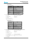
2. Place the digital multimeter probe in the V+ and V- output voltage connecter.
3. Adjust the float voltage by using a screwdriver to turn the FL point to the voltage value as shown on
the meter. The tolerance error should not exceed 0.02V.
Notes:
1. Turning the variable resistor adjustment point clockwise increases the value, and counterclockwise
2. Refer to Figure 3 (rectifier front view) for the location of V+, V- and FL point.
3. When the setting is completed, temperature and voltage compensation must be reset to the default
value.
3.3.3 Current Limit Setting
Warning: Current limit setting is not intended to be adjusted in the field. Users should only use it for
their reference.
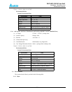
Current limit adjustment is made by turning the CL variable resistor with the digital multimeter probes
in the I+, I- test points. This current limit is set at the factory. The factory setting is always the
maximum value of 110%. For a 48V/30 Amp rectifier, the computation for the current limit is
1.1×30=33 Amps.
The following adjustment procedure is for reference only:
1. At the rectifier, place the digital multimeter probes in the I+, I- test points.
2. Place a small screwdriver in the CL adjustment point.
3. Turn the variable resistor counterclockwise to increase the value. Turn the variable resistor
clockwise to decrease the current limit value.
3.4 System Alarm
During an alarm condition, the faulty rectifier illuminates its RFA light on the front panel. The rectifier
fail alarm signal is sent to the ALU, which processes the alarm, closes the RFA alarm contacts, and lights the
alarm LEDs.
3.5 PSU Block Diagram
Refer to Figure 5.
3.6 PSU Operating Principle
After applying the incoming line voltage to the rectifier, current is applied to the EMI filter and circulates
through protection components such as the AC circuit breaker and the fuse. The major functions of the
protection devices are to prevent the rectifier from being damaged by surge voltage, to efficiently reduce the
noise of differential mode and common mode, to eliminate the high frequency noise from input current, and to
prevent noise reverse to the source circuit.
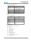
The AC input voltage is rectified and converted to a 400VDC bus through a PFC boost stage. This PFC
stage maintains the Power Factor at >.99 and the Total Harmonic Distortion (THD) at <5%.
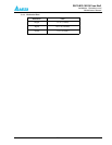
The 400 VDC bus voltages is modulated at a frequency higher than 100KHz and stepped down through a
transformer. Output of this transformer is rectified and filtered to provide the output DC voltage.


