


DS_DNM04SMD10_07162008
10
FEATURES DESCRIPTIONS (CON.)
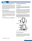
Over-Temperature Protection
The over-temperature protection consists of circuitry that
provides protection from thermal damage. If the
temperature exceeds the over-temperature threshold the
module will shut down. The module will try to restart after
shutdown. If the over-temperature condition still exists
during restart, the module will shut down again. This
restart trial will continue until the temperature is within
specification
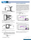
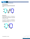
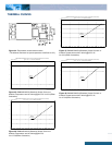
Remote Sense
The DNM/DNL provide Vo remote sensing to achieve
proper regulation at the load points and reduce effects of
distribution losses on output line. In the event of an open
remote sense line, the module shall maintain local sense
regulation through an internal resistor. The module shall
correct for a total of 0.5V of loss. The remote sense line
impedance shall be < 10Ω.
Vo
Sense
Vin
GND
RL
Distribution Losses
Distribution Losses
Distribution
L
Distribution
Figure 36: Effective circuit configuration for remote sense
operation
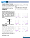
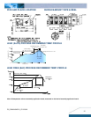
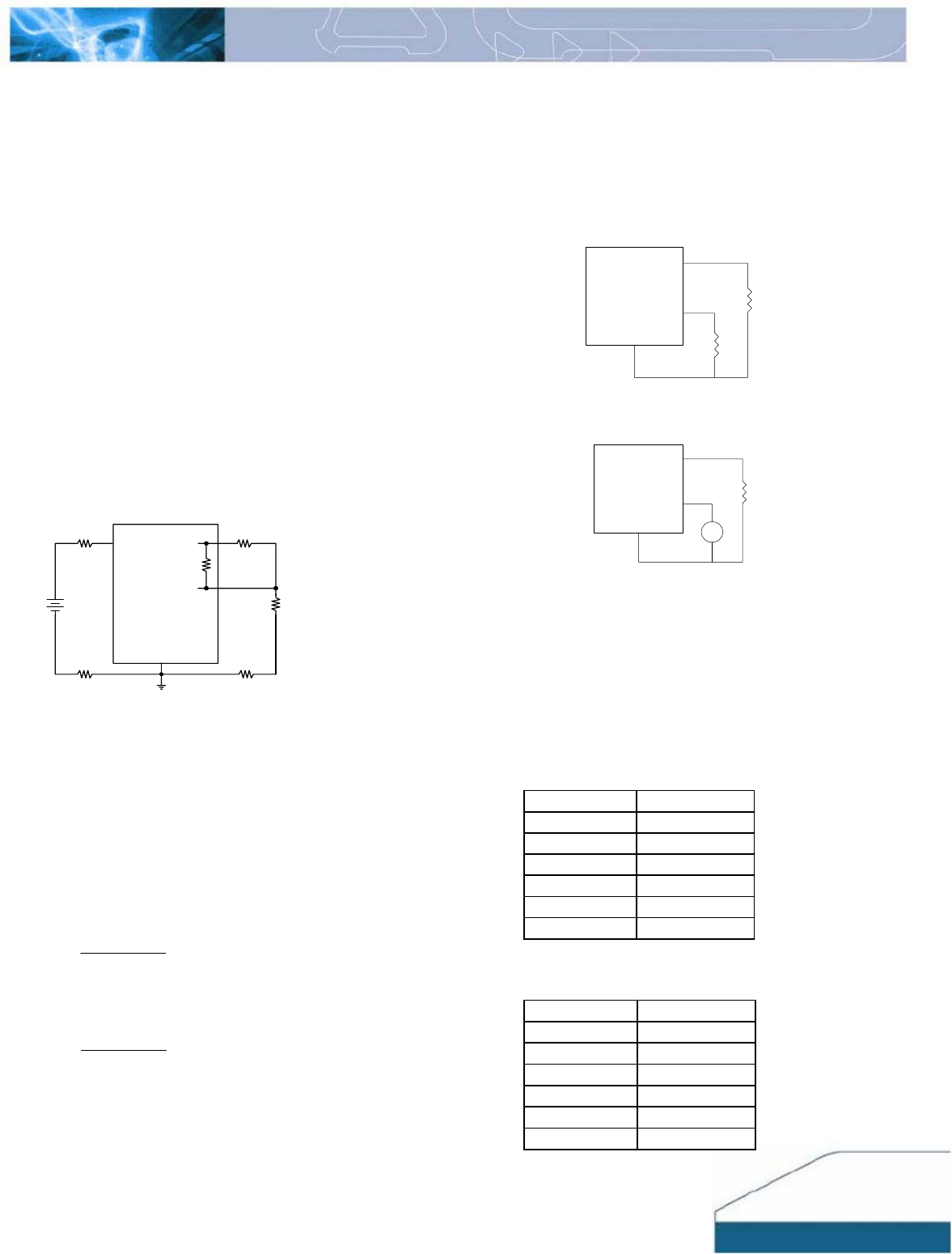
Output Voltage Programming
The output voltage of the DNM/DNL can be programmed
to any voltage between 0.75Vdc and 3.3Vdc by
connecting one resistor (shown as Rtrim in Figure 37)
between the TRIM and GND pins of the module. Without
this external resistor, the output voltage of the module is
0.7525 Vdc. To calculate the value of the resistor Rtrim
for a particular output voltage Vo, please use the
following equation:
Ω
⎥
⎦
⎤
⎢
⎣
⎡
−
−
= 5110
7525.0
21070
Vo
Rtrim
For example, to program the output voltage of the DNL
module to 1.8Vdc, Rtrim is calculated as follows:
Ω=Ω
⎥
⎦
⎤
⎢
⎣
⎡
−
−
= KRtrim 155110
7525.08.1
21070
DNL can also be programmed by apply a voltage
between the TRIM and GND pins (Figure 38). The
following equation can be used to determine the value of
Vtrim needed for a desired output voltage Vo:
(
)
7525.01698.07.0 −
×
−
=
VoVtrim
For example, to program the output voltage of a DNL
module to 3.3 Vdc, Vtrim is calculated as follows
(
)
VVtrim 267.07525.03.31698.07.0
=
−
×
−
=
Vo
TRIM
GND
RLoad
Rtrim
Figure 37: Circuit configuration for programming output voltage
using an external resistor
Vo
TRIM
GND
RLoad
Vtrim
+
_
Figure 38: Circuit Configuration for programming output voltage
using external voltage source
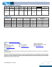
Table 1 provides Rtrim values required for some common
output voltages, while Table 2 provides value of external
voltage source, Vtrim, for the same common output
voltages. By using a 1% tolerance trim resistor, set point
tolerance of ±2% can be achieved as specified in the
electrical specification.
Table 1
Vo(V) Rtrim(KΩ)
0.7525
Open
1.2 41.97
1.5 23.08
1.8 15.00
2.5 6.95
3.3 3.16
Table 2
Vo(V) Vtrim(V)
0.7525
Open
1.2 0.624
1.5 0.573
1.8 0.522
2.5 0.403
3.3 0.267