


Preliminary DS_NE12S20A_07272007
7
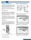
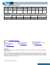
Output Voltage Programming
The output voltage of the NE series is trimmable by
connecting an external resistor between the trim pin and
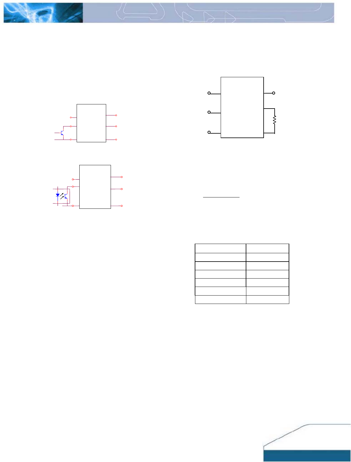
output ground as shown Figure 21 and the typical trim
resistor values are shown in Table 1.
FEATURES DESCRIPTIONS (CON.)
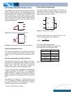
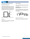
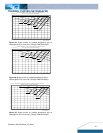
The ENABLE input can be driven in a variety of ways as
shown in Figures 19 and 20. If the ENABLE signal comes
from the primary side of the circuit, the ENABLE can be
driven through either a bipolar signal transistor (Figure
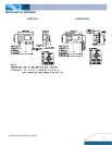
18).If the enable signal comes from the secondary side,
then an opto-coupler or other isolation devices must be
used to bring the signal across the voltage isolation
(please see Figure 19).
ND6A/10A
Vout
Ground
Trim
Enable
Ground
Vin
Figure 19: Enable Input drive circuit for NE series
Ground
Ground
ND 6A/10A
Vin
Vout
Trim
Enable
Figure 20: Enable input drive circuit example with isolation.
Input Under-Voltage Lockout
The input under-voltage lockout prevents the converte
r
from being damaged while operating when the inpu
t
voltage is too low. The lockout occurs between 3.3V to
4.3V.
Over-Current and Short-Circuit Protection
The NE series modules have non-latching over-curren
t
and short-circuit protection circuitry. When over curren
t
condition occurs, the module goes into the non-latching
hiccup mode. When the over-current condition is
removed, the module will resume normal operation.
An over current condition is detected by measuring the
voltage drop across the MOSFETs. The voltage drop
across the MOSFET is also a function of the MOSFET’s
Rds(on). Rds(on) is affected by temperature, therefore
ambient temperature will affect the current limit inception
point.
The detection of the Rds(on) of MOSFETs also acts as
an over temperature protection since high temperature
will cause the Rds(on) of the MOSFETs to increase,
eventually triggering over-current protection.
Vin Vout
Enable
Ground
Ground
Trim
ND 6A/10A
Rs
Figure 21: Trimming Output Voltage
The NE20 module has a trim range of 0.59V to 5.0V.
The trim resistor equation for the NE20A is:
591.0
1182
)(
−
=Ω
Vout
Rs
Vout is the output voltage setpoint
Rs is the resistance between Trim and Ground
Rs values should not be less than 240
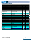
Output Voltage Rs (Ω)
0.59V
open
+1 V
2.4k
+1.5 V
1.3K
+2.5 V
619
+3.3 V
436
+5.0V
268
Table 1: Typical trim resistor values
NE2
0A
NE
2
0A
NE
2
0A