DS_S48SA1R812_06012006
[]
ΚΩ−
∆
=− 104
%Vo
up
−∆+
1089%)100(8.23 Vo
Ex. When trim-up +10% (1.8V X 1.1 = 1.98V)
Rtrim
[]
ΚΩ=−=− 9.48104
10
up
−+
1089)10100(8.23
are should be taken to ensure that the maximum
utput Voltage Adjustment (TRIM)
o increase or decrease the output voltage set point, the
Rtrim
C
output power of the module remains at or below the
maximum rated power.
O
T
modules may be connected with an external resistor
between the TRIM pin and either the Vo+ or Vo -. The
TRIM pin should be left open if this feature is not used.
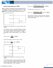
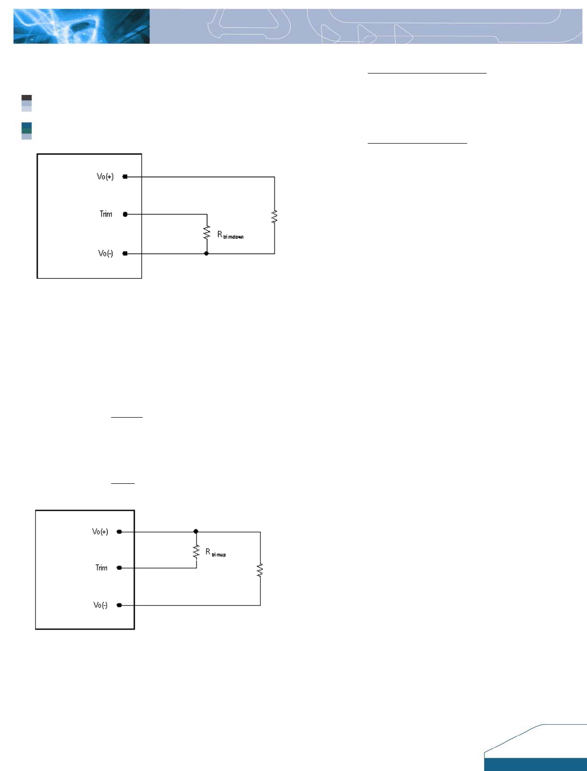
Figure 15: Circuit configuration for trim-down (decrease output
the external resistor is connected between the TRIM
voltage)
If
and Vo- pins, the output voltage set point decreases.
The external resistor value required to obtain a
percentage of output voltage change △Vo% is defined
as:
[]
ΚΩ−
∆
=− 104
%Vo
down
1089
x. When trim-down –10% (1.8V X 0.9 = 1.62V)
Rtrim
E
[]
ΚΩ=−=− 9.4104
10
down
1089
Rtrim
Figure 16: Circuit configuration for trim-up (increase output
the external resistor is connected between the TRIM
voltage)
If
and Vo+ the output voltage set point increases. The
external resistor value required to obtain a percentage
output voltage change △Vo% is defined as:
8


