


DS_NE12S06A_06302008
6
DESIGN CONSIDERATIONS
The NE12S0A0V(H)06 uses a single phase and voltage
mode controlled buck topology. The output can be
trimmed from 0.59Vdc to 5.1Vdc by a resistor from Trim
pin to Ground.
The converter can be turned ON/OFF by remote control
with positive on/off (ENABLE pin) logic. The converter DC
output is disabled when
the signal is driven low (below
0.3V). This pin is also used as the input turn on threshold
judgment. Its voltage is percent of Input voltage during
floating due to internal connection. So we do not suggest
using an active high signal (higher than 0.8V) to turn on
the module because this high level voltage will disable
UVLO function. The module will turn on when this pin is
floating and the input voltage is higher than the threshold.
The converter can protect itself by entering hiccup mode
against over current and short circuit condition. Also, the
converter will shut down when an over voltage protection
is detected.
Safety Considerations
It is recommended that the user to provide a very
fast-acting type fuse in the input line for safety. The output
voltage set-point and the output current in the application
could define the amperage rating of the fuse.
FEATURES DESCRIPTIONS
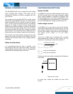
Enable (On/Off)
The ENABLE (on/off) input allows external circuitry to put
the NE converter into a low power dissipation (sleep)
mode. Positive ENABLE is available as standard. With
the active high function, the output is guaranteed to turn
on if the ENABLE pin is driven above 0.8V. The output will
turn off if the ENABLE pin voltage is pulled below 0.3V.
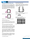
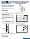
Undervoltage Lockout
The ENABLE pin is also used as input UVLO function.
Leaving the enable floating, the module will turn on if the
input voltage is higher than the turn-on threshold and turn
off if the input voltage is lower than the turn-off threshold.
The default turn-on voltage is 3.1V with 300mV
hysteresis.
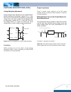
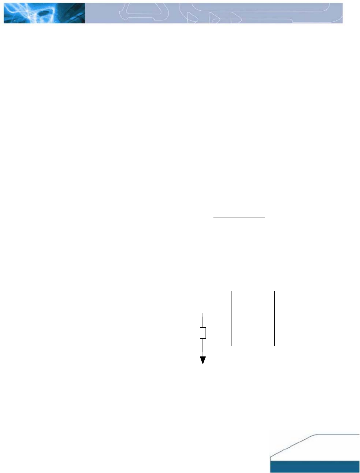
The turn-on voltage may be adjusted with a resistor
placed between the “Enable” pin and “Ground” pin. The
equation for calculating the value of this resistor is:
(
)
8.0
34.6
34.605.15
_
+
×
+
×
=
R
R
V
RTHEN
VVV
RTHENFTHEN
3.0
__
−
=
FTHEN
V
_
is the turn-off threshold
RTHEN
V
_
is the turn-on threshold
R (Kohm) is the outen resistor connected from Enable pin
to the GND
NE10A/6A
R
Enable
Fig. 18. UVLO setting
An active high voltage will disable the input UVLO
function.