


Revision October 2007, 2006PDD23000003 2-1
Chapter 2 Overview
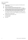
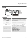
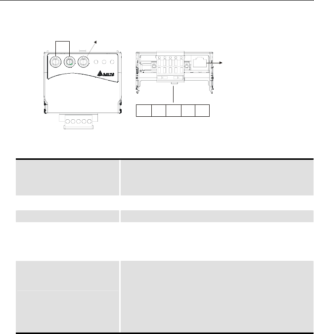
2.1 Outline
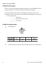
CME-DN01
ADD1 ADD2
SP
500K
250K
125K
BAUD
MODNET
MAC address Date Rate
CAN-LV+
Empty
pin
CAN-H V-
1: Reserved
2: EV
5: SG+
6: Reserved
7: Reserved
8: Reserved
3: GND
4: SG-
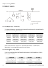
2.2 Description
Bi colors LEDs
(LED Network, LED Module
and LED SP)
provide users to analyze DeviceNet network and get the
status of the AC motor drive to solve the problem from the
Chapter 5 Troubleshooting.
MAC address used to set the physical address in the DeviceNet network.
Data rate used to set the baud rate on the DeviceNet network.
RS-485 serial port
used to connect to the AC motor drive via RJ-45. SG+ and
SG- are for the signal. Besides, the power of CME-DN01 is
provided from the AC motor drive (15V) via this port.
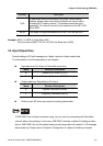
DeviceNet connection
5-pin phoenix connector is used to connect CME-DN01 to
DeviceNet network.
5-pin phoenix connector:
1. Red: V+, power supply.
2. White: CAN_H, signal high.
3. Bare: SHIELD, shield.
4. Blue: CAN_L, signa low. l
5. Black: V-, common.