SERIES
HIGH CURRENT 3-PHASE, 4-WIRE FILTERS
9-11
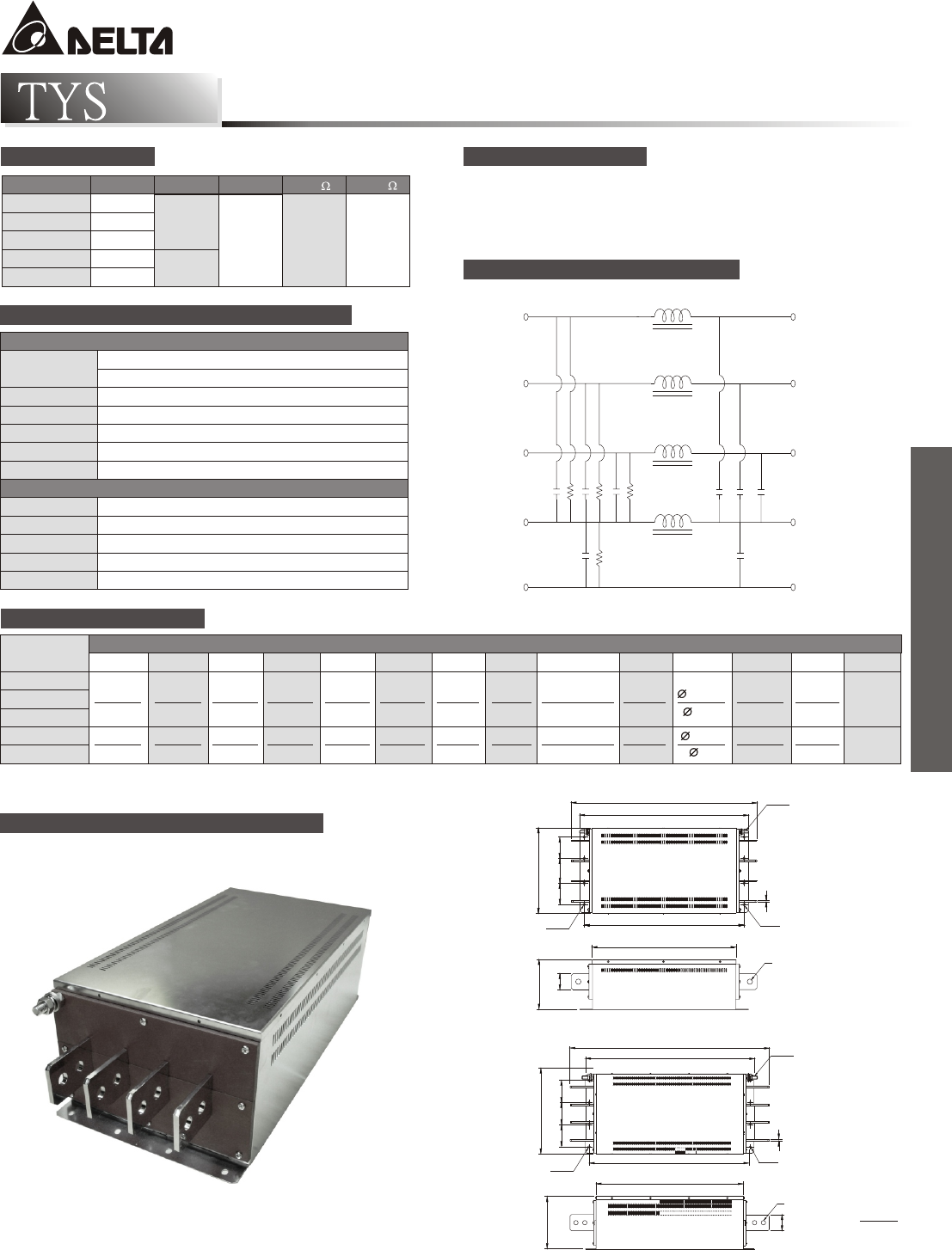
L1 L1
L
L
L
OI
AN
N
Cx
Cx
R1
R2
Cy
Cy
N
G G'
DE
L2 L2
L3 L3
ELECTRICAL SCHEMATIC
FREQUENCY-MHz
PARTNumber
.01 .05 .10 .15 .50 1.0 5.0 10 30
200TYSS104 5 15 20 20 30 30 15 10 5
300TYSS104 10 25 30 30 35 30 20 15 10
400TYSS104 10 25 30 30 30 20 10 10 5
500TYSS104 5 10 25 25 30 25 15 10 5
600TYSS104 5 10 25 25 35 30 15 10 5
200TYSS104 10 20 40 40 35 25 15 10 5
300TYSS104 25 35 35 35 35 30 20 15 10
400TYSS104 25 35 35 30 30 25 10 10 5
500TYSS104 20 20 40 40 30 25 15 10 5
600TYSS104 20 20 40 40 35 30 15 10 5
COMMON MODE (L-G) IN 50 OHM SYSTEM
DIFFERENTIAL MODE (L-L) IN 50 OHM SYSTEM
MINIMUM INSERTION LOSS IN dB
INTRODUCTIONS
1. Applications: Electric equipment, UPS, machine tool,
copy machine, automation equipment, robot, AC motor drive
2. Voltage rating: 480VAC
3. Operating frequency: 50/60Hz
MECHANICAL CONSTRUCTION
THREE-PHASE FILTERS
200~400A
B MAX.
A MAX.
N(2X)
FF
K(4X)
I(4X)
H
G
G
D MAX.D MAX.
E MAX.
M
C MAX.
L
J
INCH
UNIT:
mm
500~600A
B MAX.
A MAX.
F
I(4X)
H
G
G
J
E MAX.
M
D MAX.
K(4X)
N(2X)
C MAX.
L
COMPONENTS
200TYSS104 4.7
300TYSS104 10.0 2.2
400TYSS104 12.2 3.0 470 1M
500TYSS104 14.7
4.7
600TYSS104 20.0
PART NO. Cx(uF) Cy(uF) L(uH) R1(K ) R1(M )
SERIES DIMENSIONS
M8x1.2
M12x11.7
PARTnumber
ABCDEFGH IJKLMN
200TYSS104
20.669 18.800 15.827 9.528 5.591 17.717 2.362 2.765 0.256x0.315 0.118 0.236 0.591 1.772
300TYSS104
525.0 477.0 402.0 242.0 142.0 450.0 60.0 70.0 6.5x8.0 3.0 6.0 15.0 45.0
400TYSS104
500TYSS104 26.772 22.520 19.764 10.709 7.165 21.457 2.953 2.953 0.295x0.374 0.236 0.295 0.591 2.165
600TYSS104
DIMENSIONS IN INCHES/mm
680.0 572.0 502.0 272.0 182.0 545.0 75.0 75.0 7.5x9.5 6.0 7.5 15.0 55.0


