


1.
Warning
This instruction sheet provides information on the installation, wiring and trial operation of DVP01PU-H2. For more
detailed information, see “DVP-PLC Application Manual: Special Module”.
DO NOT touch any terminal when the power is switched on. Switch off the power before wiring.
DVP01PU-H2 is an OPEN-TYPE device and therefore should be installed in an enclosure free of airborne dust,
humidity, electric shock and vibration. The enclosure should prevent non-maintenance staff from operating the device
(e.g. key or specific tools are required to oepn the enclosure) in case danger and damage on the device may occur.
DO NOT connect input AC power supply to any of the I/O terminals; otherwise serious damage may occur. Check all
the wiring again before switching on the power.
Introduction
Model Explanation and Peripherals
DVP01PU-H2 pulse generation unit is mainly applied to the speed or position control of step or servo drive
system. The maximum output pulse of DVP01PU-H2 can be up to 200kPPS. DVP01PU-H2 is built in with
various route control modes. Through FROM/TO instructions in DVP-EH2 MPU program, the data in
DVP01PU-H2 can be read or written. There are 54 16-bit control registers (CR) in DVP001PU-H2. The
32-bit parameters are composed of 2 continuous CR#.
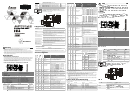
Product Profile (Indicators, Terminal Block, I/O Terminals)
Unit: mm
0VSTARTDOGL SN A -
24V S/S
B - PG0-CLR- FP - RP -
STOP LSP A + B + PG0+ CL R+F P+ FP -
8
1
DIN rail (35mm)
6
Terminals
2
Connection port for extension unit/module
7
Mounting hole
3
Model name
8
I/O terminals
4
Status indicators
9
Connection port for extension unit/module
5
DIN rail clip
LED Indicators
POWER
: Power indicator, +5V internal power is normal START
: Starting input indicator
LV : Low voltage indicator (on when the external STOP : Stopping input indicator
power supply is less than19.5V) DOG : DOG input indicator
ERROR
: Error indicator (On/Off/flash). Flashes when FP : Forward pulse output indicator
CR#44 is not 0. RP : Reverse pulse output indicator
LSP : Right limit input indicator ΦA : MPG A-phase pulse input indicator
LSN : Left limit input indicator ΦB : MPG A-phase pulse input indicator
PG0 : Zero signal input indicator CLR : Clearing signal output indicator
I/O Terminal Signals
Type
Terminal Description Response feature
Power supply
+24V, 0V Power input: 24V DC (-15 ~ +20%), Current consumption: 100mA -
START Starting input 15ms/50ms
STOP Stopping input 15ms
LSP/LSN Right/left limit input 1ms
ΦA+, ΦA- MPG A-phase pulse input +, - (differential signal input) 200kHz
ΦB+, ΦB- MPG B-phase pulse input +, - (differential signal input) 200kHz
Input
PG0+, PG0-
Zero signal input +, - (differential signal input) 1ms
ENGLISH
Input DOG
2 variations according to different operation modes:
1. DOG signal when in zero return
2. Interruption signal inserted in signal-speed or 2-speed sections
1ms
CLR+, CLR-
Clearing signal (clearing signals in the error counter in servo drive)
130ms
FP+, FP-
FP/RP mode: forward pulse output; pulse/direction: pulse output;
A/B phase: A phase output
200kHz
Output
RP+, RP-
FP/RP mode: reverse pulse output; pulse/direction: direction output;
A/B phase: B phase output
200kHz
Wiring
Less than
6.8 mm
Less than
6.8 mm
For M3.5
1. Use O-type or Y-type terminals for the I/O wiring as shown in the figure. The torque of
screw at the PLC terminal should be 5 ~ 8 kg-cm (4.3 ~ 6.9 in-lbs).
2. DO NOT place the wirings of input signals, output signals and power supply in the same
wire conduit.
3. Use only 60/75°C copper conductors.
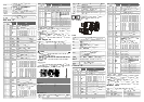
I/O Circuit
DVP01PU-H2
START
STOP
LSP
LSN
DOG
S/S
+24V
5-24VDC
+24VDC input
24V
0V
FP+
FP-
RP+
RP-
CLR+
CLR-
A phase
A+
A-
B+
PG0+
PG0-
5-24VDC
PLS
/PLS
SIGN
/SIGN
DI2
COM-
VDD
COM+
17
11
41
43
37
36
10
45
24V
B phase
B-
Delta Servo Drive
ASDA series
Shielding cable
MPG pulse
Specifications
Item Description
Power supply
24V DC (-15% ~ +20%); Current consumption: 140 ± 30mA, supplied by DVP-EH2 MPU or
other self-prepared power supplier
Max. number of
connected modules/axes
8 modules (axes), which will not occupy any I/O points. DVP-EH2 series MPU is able to
connect to max. a total of 8 extension modules.
Distance
Set up by CR. Range: -2,147,483,648 ~ +2,147,483,647; unit: um, mdeg, 10
-4
inch, Pulse;
multiplications: 10
0
, 10
1
, 10
2
, 10
3
; options: absolute position or relative displacement
Speed
Set up by CR. Range: -2,147,483,648 ~ +2,147,483,647 (10 ~ 200kPPS pulse conversion);
unit: pulse/s, cm/min, 10deg/min, inch/min
External output points
Isolated by photocoupler. LED indicators for all I/O signals.
Output points FP and RP are differential signal (5V).
Output point CLR is transistor NPN open collector (5 ~ 24V DC, less than 20mA).
External input points
Isolated by photocoupler. LED indicators for all I/O signals.
Input points START, STOP, LSP, LSN, DOG are contacts or transistor open collector (24V DC
± 10%, 5±1mA
).
Input points ΦA and ΦB are differential or transistor open collector (5 ~ 24V DC, 6 ~ 15mA
)
Input points PG0 is differential or transistor open collector (5 ~ 24V DC, 6 ~ 15mA)
Pulse output methods In 3 modes: Pulse/Dir, FP (CW)/RP (CCW), A/B; by differential output
Position control program
& data exchange with
MPU
Through FROM/TO instructions in DVP-EH2 MPU program, DVP01PU-
H2 is able to read and
write the data in the CR. If the data are 32-bit, 2 CRs will be required to process the data.
CR#0 ~ CR#53 are the built-in 16-bit control registers.
When connected to
DVP-PLC MPU in series
The modules are numbered from 0 to 7 autom
atically by their distance from MPU. No. 0 is the
closest to MPU and No. 7 is the furthest. Maximum 8 modules are allowed to connect to MPU
and will not occupy any digital I/O points.
Other Specifications
Environment
Operation/storage
Operation: 0°C ~ 55°C (temperature); 50 ~ 95% (humidity); pollution degree 2.
Storage: -25°C ~ 70°C (temperature); 5 ~ 95% (humidity)
Vibration/shock immunity
International standards: IEC 61131-2, IEC 68-2-6 (TEST Fc)/IEC 61131-2 & IEC 68-2-27
(TEST Ea)
Control Registers
CR#
HW
LW
Address
Latched
Attribute
Content Setup range
#0
H’4190
R
Model name Set up by the system. DVP01PU-H2 model code = H’6110
#2
#1
H’4191
R/W
Number of pulses required
for rotate motor for 1
revolution (A)
Range: 1 ~ +2,147,483,647 PPS/REV
Default = 2,000 pulses/revolution (PLS/REV)
#4
#3
H’4193
R/W
Distance the motor rotates
for 1 revolution (B)
Range: 1 ~ +2,147,483,647 unit/REV
Default = 1,000 (unit*1/REV)
b15
b14
b13
b12 b11
b10
b9 b8 b7 b6 b5 b4 b3 b2 b1 b0
#5
H’4195
R/W
Parameter setting
Default = H’0000
STOP
input polarity
START
input pola
rity
START
response time
Acceleration curve
options
DOG
polarity
DOG
trigger mode
Revolution direction
Zero return direction
LSN
input polarity
LSP
input polarity
Pulse output methods
Multiplication of
position data
Unit setting
#7
#6
H’4196
R/W
Maximum speed (V
MAX
)
Range: 0 ~ +2,147,483,647 unit*1 (10 ~ 200kPPS pulse
conversion)*2. Default: 200,000 unit*1
#9
#8
H’4198
R/W
Bias speed (V
BIAS
)
Range: 0 ~ +2,147,483,647 unit*1 (0 ~ 200kPPS pulse
conversion)*2. Default: 0 unit*1
#11 #10 H’419A
R/W JOG speed (V
JOG
)
Range: 0 ~ +2,147,483,647 unit*1 (10 ~ 200kPPS pulse
conversion)*2. Default: 5,000 unit*1
#13
#12
H’419C
R/W
Zero return speed (V
RT
)
Range: 0 ~ +2,147,483,647 unit*1 (10 ~ 200kPPS pulse
conversion)*2. Default: 50,000 unit*1
#15
#14
H’419E
R/W
Zero return deceleration
speed (V
CR
)
Range: 0 ~ +2,147,483,647 unit*1 (10 ~ 200kPPS pulse
conversion)*2. Default: 1,000 unit*1
#16
H’41A0
R/W
The number of PG0 in
zero return mode (N)
Range: 0 ~ +32,767PLS
Default: 0PLS
#17
H’41A1
R/W
The number of pulses in
zero return mode (P)
Range: -32,768 ~ +32,767PLS
Default: 0PLS
#18
H’41A2
R/W
Zero return mode
(H MODE)
b0: zero return mode
b1: detecting DOG falling edge in zero return mode
#20
#19
H’41A3
R/W
Setup of zero point (HP) Range: 0 ~ ±999,999 unit*1. Default: 0 unit*1
#21
H’41A5
R/W
Acceleration time (T
ACC
) Range: 10 ~ +32,767ms. Default: 100ms
#22
H’41A6
R/W
Deceleration time (T
DEC
) Range: 10 ~ +32,767ms. Default: 100ms
#24
#23
H’41A7
R/W
Target position (I) (P(I))
Range: -2,147,483,648 ~ +2,147,483,647 unit*1
(-2,147,483,648 ~ +2,147,483,647 pulse conversion) *2.
Default: 0 unit*1
#26
#25
H’41A9
R/W
Operation speed (I) (V(I))
Range: -2,147,483,648 ~ +2,147,483,647 unit*1 (10 ~
200kPPS pulse conversion)*2. Default: 1,000 unit*1
#28
#27
H’41AB
R/W
Target position (II) (P(II))
Range: -2,147,483,648 ~ +2,147,483,647 unit*1
(-2,147,483,648 ~ +2,147,483,647 pulse conversion)*2.
Default: 0 unit*1
CR#
HW
LW
Address
Latched
Attribute
Content Setup range
#30
#29
H’41AD
R/W
Operation speed (II) (V(II))
Range: 0 ~ +2,147,483,647 unit*1 (10 ~ 200kPPS pulse
conversion)*2. Default: 2,000 unit*1
b15
b14
b13
b12 b11
b10
b9 b8 b7 b6 b5 b4 b3 b2 b1 b0
#31 H’41AF
R/W
Operation instruction
Default: H’0000
-
-
CLR
output
On/Off
CLR
signal output mode
-
Clear CP
-
Software
START
Absolute position setup
Enabling zero return
Enabling
JOG-
Enabling
JOG+
Stopping reverse pulses
Stopping forward pulses
Software
STOP
Error reset
b15
b14
b13
b12
b11
b10
b9
b8
b7
b6
b5
b4
b3
b2
b1
b0
#32
H’41B0
R/W
Work mode
Default: H’0001
-
-
-
Rest to factory setting
MASK
settings
LSP/LSN
stop mode
M
anual Pulse Generator
range
STOP
mode
Manual Pulse Generator
input operation
Variable speed operation
Interrupting 2
-
speed
positioning operation
2
-
speed positioning
operation
Interrupting sing
le
-
speed
positioning operation
Single
-
speed positioning
operation
#34
#33
H’41B1
R/W
Current position CP (PLS)
Range: -2,147,483,648 ~ +2,147,483,647PLS.
Default: 0PLS
#36
#35
H’41B3
R/W
Current speed CS (PPS) Range: 0 ~ +2,147,483,647PPS.Default: 0PPS
#38
#37
H’41B5
R/W
Current position CP
(unit*1)
Range: -2,147,483,648~+2,147,483,647 unit*1
Default: 0 unit*1
#40
#39
H’41B7
R/W
Current speed CS (unit*1)
Range: 0 ~ +2,147,483,647 unit*
1
. Default: 0 unit*1
#41
H’41B9
R/W
Communica-
tion address setting
Setting up RS-485 communication address. Range: 01 ~
254.
Default: K1
#42
H’41BA
R/W
Communication speed
(baud rate) setting
For setting up communication speed:
4,800/9,600/19,200/38,400/ 57,600/115,200bps.ASCII data
format: 7-bit, even bit, 1 stop bit (7, E, 1). RTU data format:
8-bit, even bit, 1 stop bit (8, E, 1).
b0: 4,800bps. b1: 9,600 bps (D
efault).
b2: 19,200bps. b3: 38,400bps. b4: 57,600bps. b5:
115,200bps
b6 ~ b14: reserved. b15:
0=RTU mode; 1=ASCII mode
(Default).
b15
b14
b13
b12
b11
b10
b9
b8
b7
b6
b5
b4
b3
b2
b1
b0
#43
H’41BB
R/W
Execution status
Default: H’XXXX
-
-
-
-
-
MPG input counting down
MPG input counting up
-
Route pauses
Positioning is completed
Error occurred
CP
value overflows
Zero return is completed
Reverse pulse output in
progress
Forward pulse output
in
progress
Execution status
#44
H’41BC
R
Error code See “ Error Code & Troubleshooting” Default: H’0000
#45
H’41BD
R/W
Numerator of MFG
electronic gearing
See explanations below. Default: H’1.
#46
H’41BE
R/W
Denominator of MFG
electronic gearing
See explanations below. Default: H’1.
#48
#47
H’41BF
R/W
Input frequency of MPG Input pulse frequency. Default: 0.
#50
#49
H’41C1
R/W
Accumulated number of
pulses by MPG
Accumulated by the number of pulse input from MPG.
Forward pulse is accumulated by “plus” and reverse pulse
is accumulated by “minus”. The accumulated value will not
be affected by the settings in CR#45 and CR#46. Default:
0.
Set value
Response
speed
5
4ms (default)
4
32ms
3
108ms
2
256ms
#51
H’41C3
R/W
Response speed of MPG
input
1 or 0
500ms
The faster the response speed,
the more synchronous the
instruction pulse output and
MPG pulse input. The slower the
response speed, the more
possible the instruction pulse
output lags behind MPG pulse
input. (Default: 5)
bit # Status Description
b0 START input
When START input is On, b0=On.
b1 STOP input When STOP input is On, b1=On.
b2 DOG input When DOG input is On, b2=On.
b3 PG0 input When PG0 input is On, b3=On.
b4 LSP input When LSP input is On, b4=On.
b5 LSN input When LSN input is On, b5=On.
b6
A phase input
When A phase input is On,
b6=On.
b7
B phase input
When B phase input is On,
b7=On.
#52
H’41C4
R Terminal status
b8 CLR output When CLR output is On, b8=On.
#53
H’41C5
R Firmware version Displayed in hex; e.g. V1.00 is indicated as H’0100.
*1: The setting of unit is in accordance with b0 and b1 of CR#5.
*2: The module outputs the maximum pulses if the pulse conversion value exceeds the range and outputs the minimum pulses if the
conversion value falls below the range.
CR#0 ~ CR#53: The corresponding parameter addresses H’4190 ~ H’41C5 are for users to read/write data by
RS-485 communication. When using RS-485, th e user has to separate the module with MPU first.
a. Communication baud rate: 4,800/9,600/19,200/38,400/57,600/115,200bps
b. Modbus ASCII/RTU communication protocols: ASCII data format (7-bit, even bit, 1 stop bit (7, E, 1)); RTU
data format (8-bit, even bit, 1 stop bit (8, E, 1)).
c. Function: H’03 (read register data); H’06 (write 1 word datum to register); H’10 (write many word data to
register)
d. Latched CR should be written by RS-485 communication to stay latched. CR will not be latched if written
by MPU through TO/DTO instruction.
Error Code & Troubleshooting
ERROR LED will be on when hardware malfunction or incorrect parameter settings occur. The error code will
be recorded in CR#44.
Error code
Explanation Error code Explanation
H’0000 No error H’0014 Incorrect V
JOG
H’0001 Incorrect target position (I) H’0020 FP is forbidden
H’0002 Incorrect target position (II) H’0021 RP is forbidden
H’0010 Incorrect operation speed (I) H’0030 Low voltage
H’0011 Incorrect operation speed (II) H’0080 Hardware error in internal memory
H’0012 Incorrect V
CR
H’0081 Incorrect written in data in internal memory
H’0013 Incorrect V
RT
DVP01PU-H2
DVP-PLC
(Open Type) /
DVP01PU-H2 200kPPS
DVP-PLC EH2 FROM/TO
54 CR 16 bits 32 CR
( )
mm
0V S TART D OG LSN A -
24V S/S
B - PG0- CLR- FP - R P -
STOP LSP A + B + P G0+ C LR+ FP+ FP -
8
1
DIN (35mm)
6
2
/
7
3
8
4
9
/
5
DIN
POWER +5V START
LV STOP
19.5V DOG
ERROR (On/Off ) CR#44 FP
RP
LSP ΦA A
LSN ΦB B
PG0 CLR
+24V, 0V, 24V DC (-15 ~ +20%) 100mA -
START 15ms/50ms
STOP 15ms
LSP/LSN 1ms
ΦA+, ΦA- A +, - 200kHz
ΦB+, ΦB- B +, - 200kHz
PG0+, PG0- +, - 1ms
DOG
2
1. 2.
1ms
CLR+, CLR- Servo 130ms
FP+, FP-
/ /
AB A
200kHz
RP+, RP-
/ /
AB B
200kHz
1. / O Y PLC 5 ~ 8 kg-cm
(4.3 ~ 6.9 in-lbs)
2.
3. 60/75°C
DV P0 1PU -H2
START
ST OP
LS P
LS N
DO G
S/ S
+24V
5- 24V DC
+24VDC
24 V
0V
FP +
FP-
RP +
RP -
CLR+
CL R-
A
A+
A-
B+
PG 0+
PG 0-
5- 24V DC
PL S
/PLS
SI GN
/SIG N
DI 2
CO M-
VD D
CO M+
17
11
41
43
37
36
10
45
24 V
B
B-
24V DC (-15% ~ +20%) 140±30mA DVP-EH2
8 I/O DVP-EH2 8
1. -2,147,483,648 ~ +2,147,483,647 2. um, mdeg, 10
-4
inch, Pulse
3. 10
0
, 10
1
, 10
2
, 10
3
4.
1. -2,147,483,648 ~ +2,147,483,647 (10 ~ 200kPPS )
2. pulse/s, cm/min, 10deg/min, inch/min