


Warning
This Instruction Sheet only provides descriptions for installation, wiring and trial run. For further infromation,
please refer to special module of PLC Application Manual.
DO NOT touch terminals when power on. Please must power OFF before wiring.
This is an OPEN TYPE PLC. The PLC should be kept in an enclosure away from airborne dust, humidity, electric
shock risk and vibration. Also, it is equipped with protective methods such as some special tools or keys to open the
enclosure in order to prevent hazard to users or damage the PLC.
DO NOT connect the AC input power to any of the input/output terminals, or it may damage the PLC. Check all the
wiring prior to power up.
Introduction
Model Explanation & and Peripherals
DVP01PU-S (positioning unit) is mainly applied to the speed/position control of step/servo driven system. The maximum
output pulse can be up to 200 kPPS, and built-in various route control modes. The DVP-PLC SS/SA/SC/SX/SV series can
read/write DVP01PU-S via FROM/TO instrucitons. There are 49 CRs (Control Register) with 16-bit for each register in
DVP01PU-S. The 32-bits data is composed of 2 continuous CR number.
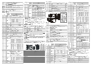
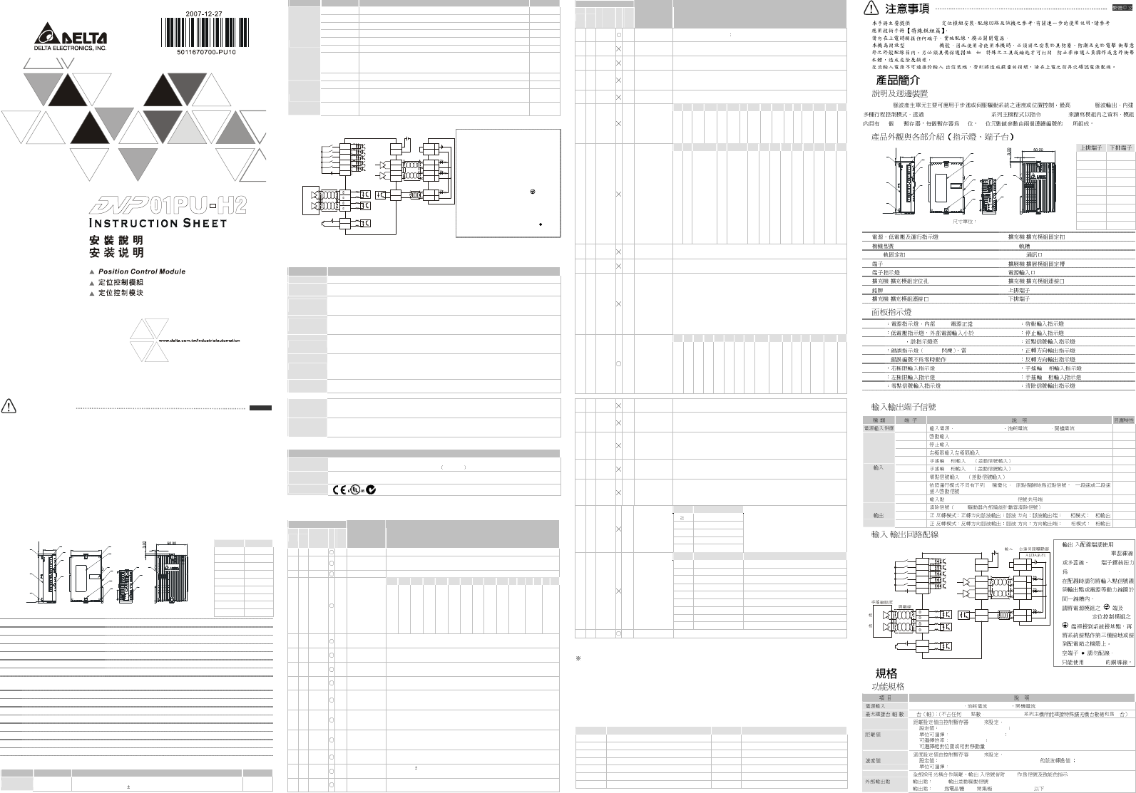
Product Profile & Outline (LED Indicator and Terminal Block)
Upper Row
Lower Row
S/S A-
START B+
STOP B-
DOG CLR+
LSP CLR-
LSN FP+
PG0+ FP-
PG0- RP+
RP
FP
CLR
DVP-01PU
START
PG0
A
B
LSN
LSP
DOG
STOP
ERROR
L.V
s
s
POWE R
3
.
0
090.00
3.00
25.20
60.00
3.40
1
2
3
14
4
5
6
8
10
3
7
9
12
11
13
15
16
Unit: mm
A+ RP-
1. Status Indicator (Power, LV and ERROR) 2. Model name 3. DIN rail clip
4. Terminal 5. Terminal indicator 6. Mounting hole
7. Nameplate 8. Extension port to connect extension module
9. Extension unit/module clip 10. DIN rail track (35mm)
11. RS-485 communication port 12. Clip for combining extension modules
13. Power input 14. Extension port to connect extension module
15. Upper row terminals 16. Lower row terminals
LED Display
POWER : Power indicator, +5V internal power START : Start input
LV : Low voltage indicator STOP
: Stop input
lit when external input power is lower than 19.5V DOG : DOG (near point signal) input
ERROR
: Error indicator (ON/OFF blinking). FP : CW pulse output
It will blink when CR#39 is not 0. RP : CCW pulse output
LSP : Right limit input indicator ΦA : A-phase input of manual pulse generator
LSN : Left limit input indicator ΦB : B-phase input of manual pulse generator
PG0 : Zero signal input indicator CLR : Output clear signal
Input/Output Terminal
Description Terminal name
Content Response
Power supply
+24V, 0V
Power input/24V DC (-15 ~ +20%)
Current consumption 70 10mA; Startup peak current 1.3 A
-
EN
G
LISH
Description Terminal name
Content Response
START Start input terminal 4ms/12ms
STOP Stop input terminal 4ms
LSP/LSN Limit Stroke of right/left limit 1ms
ΦA+, ΦA- A-phase terminal (+, -) of manual pulse generator input (line driver input) 200kHz
ΦB+, ΦB- B-phase terminal (+, -) of manual pulse generator input (line driver input) 200kHz
PG0+, PG0- Zero signal input terminal +, - (line driver input) 4ms
DOG
Offers two different functions depending on operation mode.
(1) It is near-point signal in zero return mode.
(2) It is start signal on interrupt 1st or interrupt 2nd speed mode.
1ms
Input
S/S Signal common terminal of these Inputs (START, STOP, DOG, LSP, LSN) -
CLR+, CLR- Clear signal (clear signal of internal error counter for Servo drive) 4ms
FP+, FP-
FP/RP mode: CW pulse output I/O mode: Output pulse
AB-phase mode: A-phase output
200kHz
Output
RP+, RP-
FP/RP mode: CCW pulse output I/O mode: direction output
AB-phase mode: B-phase output
200kHz
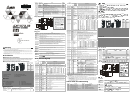
Input/Output Circuit
DVP0 1PU -S
START
STO P
LSP
LSN
DOG
S/S
+2 4V
5-2 4VD C
+24VDC IN
24V
0V
FP+
FP-
RP+
RP-
CLR+
CLR-
A-p hase
A+
A-
B+
PG 0+
PG0-
5-2 4VD C
PLS
/PLS
SIGN
/SIG N
DI2
CO M-
VDD
CO M+
17
11
41
43
37
36
10
45
24V
B-p hase
B-
Delt a Servo
ASD A series
Ma nual pulse ge nerato r
Shie lded cable
1. Please use 22-16AWG (1.5mm)
wiring (either single or multiple core)
for I/O wiring terminals. PLC
terminal screws should be tightened
to 1.95 kg-cm (1.7in-lbs). Use
copper conductors only, 60/75oC.
2. DO NOT arrange the wiring of I/O
signal wires or power supply in the
same wiring duct.
3. Make sure the terminals of
power module and DVP01PU-S are
properly grounded or connected to
the cover of power distribution
cabinet.
4. DO NOT wire to null terminal .
5. Use only 60/75°C copper conductors.
Specifications
Functions
Item Content
Power supply 24V DC (-15% ~ +20%); Current consumption 70±10mA; Startup peak current 1.3 A
Max. number of
connected axes
8 units; (SS/SA/SX/SC/SV series MPU can connect up to 8 extension modules without occupying any
I/O)
Distance
instruction
Distance value is set by CR
1. Setting range: -2,147,483,648 ~ +2,147,483,647; 2. Selectable unit: um, mdeg, 10
-4
inch, Pulse;
3. Selectable rate: 10
0
, 10
1
, 10
2
, 10
3
;
4. Selectable position: absolute and relative position instruction
Speed
instruction
Speed value is set by CR
1. Setting range: -2,147,483,648 ~ +2,147,483,647 (conversion value of 10 ~ 200 kPPS pulse)
2. Selectable unit: pulse/s, cm/min, 10deg/min, inch/min
External output
Photo coupler is for insulation and there are LED indications for all output/input signals
Outputs: FP and RP (line driver output 5V)
Output: CLR is the type of NPN open collector transistor output (5 ~ 24V DC, less than 20mA)
External input
Photo coupler is for insulation and there are LED indications for all output/input signals.
Input point: START, STOP, LSP, LSN, DOG(contact or open collector transistor, 24V DC±10%, 5±1mA)
Inputs: ΦA, ΦB (line driver or open collector transistor, 5 ~ 24V DC, 6 ~15mA)
Input: PG0 (line driver or open collector transistor, 5 ~ 24V DC, 6 ~ 15mA)
Pulse output
format
Three selectable modes: Pulse/Dir, FP (CW)/RP (CCW), A/B (all modes are line driver output).
Position
program & data
transmission
CR data can be read/write via FROM/TO intruction of PLC MPU. The 32-bit data is composed of 2
continuous CR number. The range of 16-bit CR is CR#0 ~ CR#48.
Connect to
DVP-PLC
series
Modules are numbered from 0 ~ 7 with 0 closet and 7 farthest to the MPU. Up to 8 modules can be
connected without occupying any digital I/O.
Others
Environmental specifications
Operation
/Storage
1. Operation: 0°C~ 55°C (Temperature), 50 ~ 95% (Humidity), pollution degree 2
2. Storage: -25°C~ 70°C (Temperature), 5 ~ 95% Humidity
Vibration /Shock
immunity
Standard: IEC 61131-2, IEC 68-2-6 (TEST Fc)/IEC 61131-2 & IEC 68-2-27 (TEST Ea)
Approvals
CR (Control Register)
CR No.
HM LW
Address
Latched
Attribute
Content Setting Range
#0
H’4190
R
Model No.
System setting, Read-only (The model number of DVP01PU-S is H’0110.)
#2
#1
H’4191
R/W
Pulse rate (A)
Range: 1 ~ +2,147,483,647 PPS/REV, factory setting: 2,000
Pulse/Revolution (PLS/REV)
#4
#3
H’4193
R/W
Feed rate (B)
Range: 1 ~ +2,147,483,647 unit/REV, factory setting: 1,000 (unit*1/REV)
b15
b14
b13
b12
b11
b10
b9
b8
b7
b6
b5
b4
b3
b2
b1
b0
#5
H’4195
R/W
Parameter
setting
Factory setting:
H’0000
STOP
input polarity
START input polarity
START response
time
Acceleration curve
options
DOG
polarity
DOG trigger time
Pulse direction
Zero return direction
LSN input polarity
LSP input polarity
Pulse output format
Position rate setting
Unit setting
#7 #6 H’4196
R/W
Maximum
speed V
max
Range: 0 ~ +2,147,483,647 unit*1 (10 ~ 200 kPPS) *2
Factory setting: 200,000 unit*1
#9
#8
H’4198
R/W
Bias speed
V
bias
Range: 0 ~ +2,147,483,647 unit*1 (0 ~ 200 kPPS pulse transfer value) *2
Factory setting: 0 unit*1
#11
#10
H’419A
R/W
JOG speed
V
JOG
Range: 0 ~ +2,147,483,647 unit*1 (10 ~ 200 kPPS pulse transfer value) *2
Factory setting: 5,000 unit*1
#13
#12
H’419C
R/W
Zero return
speed V
RT
Range: 0 ~ +2,147,483,647 unit*1 (10 ~ 200 kPPS pulse transfer value) *2
Factory setting: 50,000 unit*1
#15
#14
H’419E
R/W
Zero return
deceleration
speed V
CR
Range: 0 ~ +2,147,483,647 unit*1 (10 ~ 200 kPPS pulse transfer value) *2
Factory setting: 1,000 unit*1
#16
H’41A0
R/W
The number of
PG0 in zero
return mode N
Range: 0 ~ +32,767 PLS
Factory setting: 0 PLS
#17
H’41A1
R/W
The number of
pulse in zero
return mode P
Range: -32,768 ~ +32,767 PLS
Factory setting: 0 PLS
#18
H’41A2
R/W
Zero return
mode H Mode
b0: zero return mode,
b1: detect DOG falling-edge in zero return mode
#20
#19
H’41A3
R/W
Zero point
setting (HP)
Range: 0 ~ 999,999 unit*1
Factory setting: 0 unit*1
#21
H’41A5
R/W
Acceleration
time T
acc
Range: 10 ~ +32,767 ms
Factory setting: 100 ms
CR No.
HM
LW
Address
Latched
Attribute
Content Setting Range
#22
H’41A6
R/W
Deceleration time
T
dec
Range: 10 ~ +32,767 ms factory setting: 100 ms
#24
#23
H’41A7
R/W
Target
position (I) P(I)
Range: -2,147,483,648 ~ +2,147,483,647 unit*1 (-2,147,483,648 ~
+2,147,483,647 pulse transfer value) *2; factory setting: 0 unit*1
#26
#25
H’41A9
R/W
Running
speed (I) V(I)
Range: -2,147,483,648 ~ +2,147,483,647 unit*1 (10 ~ 200 kPPS pulse
transfer value) *2; factory setting: 1,000 unit*1
#28
#27
H’41AB
R/W
Target
position (II)
P(II)
Range: -2,147,483,648 ~ +2,147,483,647 unit*1 (-2,147,483,648 ~
+2,147,483,647 pulse transfer value) *2, factory setting: 0 unit*1
#30
#29
H’41AD
R/W
Running
speed (II) V(II)
Range: 0 ~ +2,147,483,647 unit*1 (10 ~ 200 kPPS pulse transfer value) *2
Factory setting: 2,000 unit*1
b15
b14
b13
b12
b11
b10
b9
b8
b7
b6
b5
b4
b3
b2
b1
b0
#31
H’41AF
R/W
Running
instruction
factory setting:
H’0000
-
-
CLR output
(
On
/Off)
CLR signal
output mode
-
Current
position
= 0
-
Software
START
ABS/REL
Coordinate
Zero return
start
JOG-
JOG+
CCW pulse
STOP
CW pulse
STOP
Software
STOP
Error reset
b15
b14
b13 b12
b11~b9
b8
b7
b6
b5
b4
b3
b2
b1
b0
#32
H’41B0
R/W
Work mode
Factory setting:
H’0001
-
-
Current position: CR34, 33; current
speed: CR36, 35;
display unit: 0
pulse, 1
unit
Return to
factory
setting
MASK setting
LSP/LSN stop mode
Manual pulse generator range limitation
STOP mode
Manual pulse generator input operation
Variable speed operation mode start
Interrupt 2
nd
-speed position mode start
2
nd
-speed position mode start
Interrupt 1
st
-speed position
mode start
1
st
-speed position mode start
#34
#33
H’41B1
R/W
Current position
CP (PLS)
Range display: -2,147,483,648 ~ +2,147,483,647 PLS
Factory setting: 0 PLS
#36
#35
H’41B3
R/W
Current speed
CS (PPS)
Range display: 0 ~ +2,147,483,647 PPS
Factory setting: 0 PPS
#37
H’41B5
R/W
Communication
address and
Baud rate
setting
RS-485 communication address setting: setting range 01 ~ 254
Factory setting: K1. Baud rate setting: 4,800, 9,600, 19,200, 38,400, 57,600,
and 115,200 bps. ASCII mode data format is 7Bit, even bit and 1 stop bit (7 E
1). RTU mode data format is 8Bit, even bit and 1 stop bit (8 E 1)
b0: 4,800 bps (bit/sec.), b1: 9,600 bps (bit/sec.) (factory setting)
b2: 19,200 bps (bit/sec.), b3: 38,400 bps (bit/sec.)
b4: 57,600 bps (bit/sec.), b5: 115,200 bps (bit/sec.)
b6: reserved, b7: 0 for RTU, 1 for ASCII mode,
b8 ~ b15: communication address
b15
b14
b13
b12
b11
b10
b9
b8
b7
b6
b5
b4
b3
b2
b1
b0
#38
H’41B6
R/W
Execution
status
factory setting:
H’XXXX
-
-
-
-
-
MPG input downward
MPG input upward
-
Route paused
indication
Position completed
indication
Error occurred flag
CP value overflow
Zero return is done
CCW pulse is
outputting
CW pulse is
outputting
Status indication
#39
H’41B7
R
Error code
Please refer to “Error Code & Troubleshooting” for detail.
Factory setting: H’0000
#40
H’41B8
R/W
Electronic
gearing number
of MPG input
Please refer to the following explanation
Factory setting: H’1
#41
H’41B9
R/W
Electronic
gearing
denominator of
MPG input
Please refer to the following explanation
Factory setting: H’1
#43
#42
H’41BA
R/W
Input frequency
of manual
pulse generator
The input frequency of manual pulse generator
Factory setting: 0
#45
#44
H’41BC
R/W
Accumulated
pulse input no.
of manual
pulse generator
The count value of CW manual pulse input is “ +” symbol, on the contrary, the
CCW manual pulse input is “-“symbol. And the count value is nothing to do
with the ratio setting of manual electronic gearing (CR#40, #41). Factory
setting: 0.
Value
Response speed
5 4ms (factory setting)
4 32ms
3 108ms
2 256ms
#46
H’41BE
R/W
Response
speed of
manual pulse
generator
1 or 0
500ms
When response speed setting is faster, the
instructions of pulse output and manual
pulse generator input will be more
synchronous. When
response speed setting
is slower, the instruction of pulse output is
slower than the instruction of manual pulse
generator input. Factory setting: 5
bit #
Status Description
b0 START input When START input is On, b0 is On.
b1 STOP input When STOP input is On, b1 is On.
b2 DOG input When DOG input is On, b2 is On.
b3 PG0 input When PG0 input is On, b3 is On.
b4 LSP input When LSP input is On, b4 is On.
b5 LSN input When LSN input is On, b5 is On.
b6 A phase input When A phase input is On, b6 is On.
b7 B phase input When B phase input is On, b7 is On.
#47
H’41BF
R
Terminal status
b8 CLR output When CLR output is On, b8 is On.
#48
H’41C0
R
System version
System version is in hexadecimal. e.g. software V1.00 is for H’0100.
*1: Unit setting varies based on b0 and b1 setting of CR#5.
*2: Use max. Pulse output if upper limit is exceeded. Use min. pulse output if lower limit is exceeded.
CR#0 ~ CR48: user can use the corresponding addresses H
’
4190 ~ 41C0 to read/write data via RS-485
communication.
1. Baud rate supportive: 4,800, 9,600, 38,400, 57,600, and 115,200 bps.
2. Modbus ASCII/RTU: ASCII mode is 7 bits, even bit and 1 stop bit (7, E, 1). RTU mode is 8 bits, even bit
and 1 stop bit (8, E, 1).
3. Function code: 03’H for read data from CR; 06’H for write one word in CR; 10’H for write many words in
CR. It indicates DVP01PU-S hardware malfunction or error parameter setting when error LED flashes.
ERR code is recorded in CR#39.
Error Code & Troubleshooting
Error code Description Error code Description
H’0000 No error H’0014 JOG speed (V
JOG
) setting error
H’0001 Target position (I) setting error H’0020 CW pulse is forbidden
H’0002 Target address (II) setting error H’0021 CCW pulse is forbidden
H’0010 Running speed (I) setting error H’0030 Low voltage
H’0011 Running speed (II) setting error H’0080 Hardware error in internal memory
H’0012 Zero return deceleration (V
CR
) setting error H’0081 Data write in error in internal memory
H’0013 Zero return (V
RT
) setting error
DVP01PU-S DVP-PLC
(Open Type) /
( : )
/
DVP01PU-S 200 kPPS
DVP-PLC SS/SA/SX/SC/SV FROM/TO
49 CR 16 32 CR
S/S A-
START B+
STOP B-
DOG CLR+
LSP CLR-
LSN FP+
PG0+ FP-
PG0- RP+
RP
FP
CLR
DVP-01PU
STAR T
PG0
A
B
LSN
LSP
DOG
STOP
ERR OR
L. V
s
s
POWER
3
.
0
0
90.00
3.00
25.20
60.00
3.40
1
2
3
14
4
5
6
8
10
3
7
9
12
11
13
15
16
mm
A+ RP-
1. 9. /
2. 10. DIN (35mm)
3. DIN 11. RS-485
4. 12. /
5. 13.
6. / 14. /
7. 15.
8. / 16.
POWER
+5V START
LV STOP
19.5V DOG
ERROR On/Off CR#39 FP
RP
LSP ΦA A
LSN ΦB B
PG0 CLR
+24V, 0V, 24V DC (-15 ~ +20%) 70±10mA 1.3 A -
START 4ms/12ms
STOP 4ms
LSP/LSN 1ms
ΦA+, ΦA- A +, - 200kHz
ΦB+, ΦB- B +, - 200kHz
PG0+, PG0- +, - 4ms
DOG
2 1. 2.
1ms
S/S (START, STOP, DOG, LSP, LSN) -
CLR+, CLR- Servo 4ms
FP+, FP- / / AB A 200kHz
RP+, RP- / / AB B 200kHz
/
DVP01PU-S
START
STOP
LSP
LSN
DOG
S/S
+24V
5-24VDC
+24VDC
24V
0V
FP+
FP-
RP+
RP-
CLR+
CLR-
A
A+
A-
B+
PG0+
PG0-
5-24VDC
PLS
/PLS
SIGN
/SIGN
DI2
COM-
VDD
COM+
17
11
41
43
37
36
10
45
24V
B
B-
1. /
22-16AWG (1.5mm)
PLC
1.95 kg-cm (1.7lb-in)
2.
3.
DVP01PU-S
4.
5. 60/75°C
24V DC (-15% ~ +20%) 70 ±10mA 1.3 A
( ) 8 I/O SS/SA/SX/SC/SV 8
(CR)
1. -2,147,483,648 ~ +2,147,483,647
2. um, mdeg, 10
-4
inch, Pulse
3. 10
0
, 10
1
, 10
2
, 10
3
4.
(CR)
1. -2,147,483,648 ~ +2,147,483,647 (10 ~ 200kPPS )
2. Pulse/s, cm/min, 10deg/min, inch/min
/ LED
FP, RP 5V
CLR NPN 5 ~ 24V DC, 20mA