


bps. b0: 4800bps, b1: 9600bps, (factory setting) b2: 19200bps, b3: 38400 bps, b4: 57600 bps, b5:
115200 bps, b6-b13: reserved, b14: exchange low and high byte of CRC check code. (RTU mode
only) b15=0: ASCII mode, b15=1: RTU mode. Communication format: ASCII mode is 7Bit, even bit,
1 stop bit (7 E 1), while RTU mode is 8Bit, even bit, 1 stop bit (8 E 1).
10. CR#33 is used to set the internal function priority. For example: characteristic register. Output
latched function will save output setting to the internal memory before power loss.
11. CR#34 is software version of model type.
12. CR#35~ CR#48 are used for system.
13. The corresponding parameters address H4032~H4063 of CR#0~CR#48 are provided for user to
read/write data via RS-485.
A. Communication baud rate: 4800, 9600, 19200, 38400, 57600, 115200 bps.
B. Communication format: ASCII mode is 7Bit, even bit, 1 stop bit (7 E 1). Communication
format of RTU mode is 8Bit, even bit, 1 stop bit (8 E 1).
C. Function code: 03H—read data from register. 06H—write one WORD to register. 10H—write
multiple WORD to register.
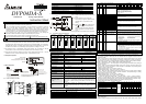
5 ADJUST D/A CONVERSION CHARACTERISTIC CURVE
5.1 Adjust D/A Conversion Characteristic Curve
Voltage output mode:
Mode 0 of CR#1: GAIN = 5V(2000
LSB
),
OFFSET=0V (0
LSB
)
Mode 1 of CR#1: GAIN = 6V(2400
LSB
),
OFFSET=2V (800
LSB
).
GAIN: The setting range of voltage output value when
digital input value is K2000 should be
-4V~+20V(-1600
LSB
~+8000
LSB
).
OFFSET: The setting range of voltage output value when
digital input value is K0 should be
-5V~+5V(-2000
LSB
~ +2000
LSB
).
0
+2000 +4000
2V
5V
6V
10V
OFFSET
GAIN
voltage
output
Digital input
mode 0
mode 1
GAIN-OFFSET:
Setting range: +1V~+15V (+400
LSB
~ +6000
LSB
).
Current output mode
Mode 2 of CR#1: GAIN = 12mA (2400
LSB
),
OFFSET=4mA (800
LSB
).
Mode 3 of CR#1: GAIN = 10mA (2000
LSB
),
OFFSET=0mA (0
LSB
).
GAIN: The setting range of current output when digital
input value is K2000 should be -8mA~+40mA
(-1600
LSB
~+8000
LSB
).
OFFSET: The setting range of current output when digital
input value is K0 should be -10mA ~+10mA
(-2000
LSB
~+2000
LSB
).
0
+2000 +4000
20mA
OFFSET
GAIN
12mA
10mA
4mA
current
output
digital input
mode 3
mode 2
GAIN-OFFSET:
Setting range: +2mA~+30mA (+400
LSB
~+6000
LSB
).
The charts above are D/A conversion characteristic curve of voltage input mode and current input
mode. Users can adjust conversion characteristic curve by changing OFFSET values (CR#18~CR#21)
and GAIN values (CR#24~CR#27) depend on application.
LSB (Least Significant Bit): 1.voltage output: 1
LSB
=10V/4000=2.5mV. 2.current output:
1
LSB
=20mA/4000=5µA.
5.2 Program Example for Adjusting D/A Conversion Characteristics Curve
Example 1: Setting OFFSET value of CH1 to 0V(=K0
LSB
) and GAIN value is 2.5V(=K1000
LSB
).
X0
K1000
K24
H10 K1
K1
H0 K1
M1002
K33
K1
K1
K18
K0
TO
TO
TO
TO
K1
K1
K1
K1
Writing H10 to CR#1 of analog output
module#0. Setting CH1 to mode 0
(voltage output 0V~ +10V) and CH2 to
mode 2 (current output 4mA~ +20mA).
Writing H0 to CR#33 and allow CH1 ~
CH4 to adjust characteristic.
When X0 switches from Off to On,
K0
LSB
of OFFSET value will be written
to CR#18 and K1000
LSB
of GAIN value
will be written to CR#24.
Example 2: Setting OFFSET value of CH2 to 2mA (=K400
LSB
) and GAIN value to 18mA (=K3600
LSB
).
X0
K1
K1
H0 K1
M1002
K33
K1
K1
H18
K19
K25
K400
K3600
TO
TO
TO
TO
K1
K1
K1
K1
Writing H10 to CR#1 of analog output
module#0. Setting CH1 to mode 0
(voltage output 0V~ +10V) and CH2 to
mode 3 (current output 0mA~ +20mA).
Writing H0 to CR#33 and allow CH1 ~
CH4 to adjust characteristic.
When X0 switches from Off to On,
K400
LSB
of OFFSET value will be
written to CR#19 and K3600
LSB
of
GAIN value will be written to CR#25.
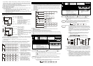
6 INITIAL PLC START-UP
Lamp display
1. When power is on, POWER LED will be lit and ERROR LED will be lit for 0.5 second.
2. It is normal that POWER LED should be lit and ERROR LED should turn off. When power supply
is lower than 19.5V, ERROR LED will blink continuously till the power voltage is higher than 19.5V.
3. When it connects to PLC MPU in series, RUN LED on MPU will be lit and A/D LED or D/A LED
should blink.
4. After receiving the first RS-485 command during controlling via RS-485, A/D LED or D/A LED
should blink.
5. After converting, ERROR LED should blink if input or output exceeds the upper bound or below
the lower bound.
Program example:
M0
K1
M1000
FROM
END
D0
TO
K0K1
D0CMP H89
INC D100
ADD D101 K5
LD= K4000 RST
H10
K2K6
M1
M1013
D101
D100 D100
LD=
K4000
RST
D101D101
K1 K1 K1
TO
M1
K1
D100
Explanation:
Read the data of model type from expansion module K1 and distinguish if the data is H89
(DVP04DA-S model type).
D100 will increase K1 and D101 will increase K5 every second.
When value of D100 and D101 attain to K4000, they will be reset to 0.
If the model type is DVP04DA-S, M1 will be on and set the output mode: CH1 mode to 0, CH2 mode
to 2.
Writing output setting CR#6 and CR#7 to D100 and D101. Analog output will vary with D100 and D101
value.
7 COMMAND EXPLANATION
API
Adaptive model
ES EP EH
78
D
FROM
P
Read special module
CR data
Bit device Word device
X Y M S K H KnX KnY KnM KnS T C D E F
m
1
¼ ¼
m
2
¼ ¼
D ¼ ¼ ¼ ¼ ¼ ¼ ¼ ¼
n ¼ ¼
Note: The usage range of operand m
1
is 0~7.
The usage range of operand m
2
: ES/EP:
0-48, EH: 0-254.
The usage range of operand n: ES/EP: n=
1~(49-m2), EH: 1~(255-m2).
ES series model doesn’t support pulse
execution command (FROMP, DFROMP).
16-bit command (9 STEPS)
FROM
Continuous
execution
FROMP
Pulse
execution
32-bit command (17 STEPS)
DFROM
Continuous
execution
DFROMP
Pulse
execution
Flag: When M1083 on, it allows enable
the interrupt during FROM/TO.
Refer to following for detail.
Command
Explanation
: the number for special module. : the number of CR (Control Register) of
special module that will be read.
: the location to save reading data. : the
data number of reading ONCE.
DVP-series PLC uses this command to read CR data of special module.
: When assign the bit operand, K1~K4 are used for 16-bit and K5~K8 are used for
32-bit.
Please refer the footnote below for calculation the special module number.
Program
Example
Read the content of CR#24 of special module#0 save it to D0 of PLC, and read the
content of CR#25 of special module#0 save it to D1 of PLC. 2 data are read in one
time when n=2.
Command will be executed when X0=ON. Command won’t be executed if X0=OFF
and the content of previous reading data won’t change.
X0
FROM K0 K24 D0 K2
API
Adaptive model
ES EP EH
79
D
TO
P
Special module CR
data write in
Bit device Word device
X Y M S K H KnX KnY KnM KnS T C D E F
m
1
¼ ¼
m
2
¼ ¼
S ¼ ¼ ¼ ¼ ¼ ¼ ¼ ¼ ¼ ¼ ¼
n ¼ ¼
Note: The usage range of operand m
1
is 0~7.
The usage range of operand m
2
: ES/EP:
0-48, EH: 0-254.
The usage range of operand n: ES/EP:
1~(49-m2), EH: 1~(255-m2).
For ES series, it doesn’t support pulse
execution command (TOP, DTOP)
16-bit command (9 STEPS)
TO
Continuous
execution
TOP
Pulse
execution
32-bit command (17 STEPS)
DTO
Continuous
execution
DTOP
Pulse
execution
Flag: When M1083 on, it allows to
enable the interrupt during
FROM/TO. Refer to below for
detail.
Command
Explanation
: the number of special module. : the number of CR (Control Register) of
special module that will be wrote in.
: the data to write in CR. : the data
number to write in one time.
DVP-series PLC uses this command to write data into CR of special module.
: When assigning bit operand, K1~K4 can be used for 16-bit and K5~K8 can be
used for 32-bit.
Program
Example
Use 32-bit command DTO, program will write D11 and D10 to CR#3 and CR#2 of
special module#0. It only writes one group of data in one time when=1.
Command will be executed when X0=ON, will not be executed when X0=OFF. The
previous write data won’t be changed.
X0
K0 K2 D0DTO
K1
Footnote
The rule of command operand
m1: arrangement number of special module. The number of special module
that connects to PLC MPU. The number sequence of special module from the
closest to the furthest of MPU is from 0 to 7. 8 modules is the max and it won’t
occupy I/O point.
m2: the number of CR. There are 49 CR (Control Register) with 16-bit each
built-in memory in the special module. The number of CR uses decimal digital
(#0~#48). All running status and setting values of special module have
included.
FROM/TO command is used to read/write CR data 1pcs at a time, while
DFROM/DTO command is used to read/write CR data 2pcs in one time.
CR #10 CR #9
Upper 16-bit
Lower 16-bit
Specified CR number
The number of transmission groups n. The meaning of n=2 of 16-bit
command and n=1 of 32-bit are the same.
D0
D1
D2
D3
D4
D5
CR #5
CR #6
CR #7
CR #8
CR #9
CR #10
D0
D1
D2
D3
D4
D5
CR #5
CR #6
CR #7
CR #8
CR #9
CR #10
Specified device
Specified C
R
Specified device
Specified CR
16-bit command when n=6
32-bit command when n=3
In ES series models, flag M1083 is not provided. All interrupts (including external or
internal interrupt subroutines) will be disabled when FROM/TO command is
executed. Interrupts will be resumed after FROM/TO command complete. Please be
advised FROM/TO command also can be executed in the interrupt subroutine.
The function of the flag M1083 (FROM/TO mode exchange) provided in EP/EH
series models:
A. When M1083=Off, all interrupts (including external or internal interrupt
subroutines) will be disabled when FROM/TO command is executed. The
Interrupts will resumed after FROM/TO command complete. Please be
advised FROM/TO command can be executed in the interrupt subroutine.
B. When M1083=On, if an interrupt enable occurs while FROM/TO command
are executing, the interrupt FROM/TO command will be blocked till the
requested interrupt finish. Unlike M1080 off situation, FROM/TO command
cannot be executed in the interrupt subroutine.