


http://www.delta.com.tw/products/plc.asp
DVP04PT-S
DVP04PT-S Platinum Temperature Sensors
Instruction Sheet
1
WARNING
Please carefully read this instruction thoroughly prior to use the DVP04PT-S.
In order to prevent electric shock, do not touch the terminals or conduct any maintenance while
PLC power is ON.
DO NOT open the PLC. Only qualified personel or Delta staff is allowed to
conduct any internal electrical work on the PLC.
This is an OPEN-TYPE device and certified to meet IEC 61131-2 (UL 508) safety requirements
when installed in an enclosure.
The DVP04PT-S must be kept under the environment away from high temperatures, high humidity,
exceessive vibration, corrosive gases, liquids, airborne dust, and metallic particles.
Do not apply AC power to any of the input/output terminals, or it may damage the DVP04PT-S.
Make sure that the DVP04PT-S is properly grounded , to prevent any electromagnetic noise.
Use wires with resistance when connecting the platinum resistance thermister (RTD) to the PLC.
Please keep the wires as short as possible when connecting RTD to PLC and keep power lead
as far away as possible from I/O wires to prevent noise interference.
2
INTRODUCTION
2.1 Model Explanation and Peripherals
Thank you for choosing DELTA DVP Series PLC. The DVP04PT-S allows the connection of four
platinum temperature sensors (PT100 3-WIRE 100Ω 3850 PPM/°C(DIN 43760 JIS C1604-1989)).
The PLC converts the sensors input to a 14-bit digital signal, which then be manipulated using TO
and FROM commands in the ladder logic program. There are 49 Controlled Registers (CR, each
register has 16-bit) in each module.
DVP04PT-S is able to share the information via RS-485 communication or by direct connect to
DVP-SS main processing unit. Power supply and main processing units are sold separately.
DVP04PT-S displays both Centigrade and Fahrenheit. The input resolution for Centigrade is 0.1
degrees and for Fahrenheit is 0.18 degrees.
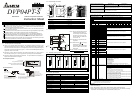
Nameplate Explanation
04PT-S0T3250003VX.X
20.4VDC ~ 26.4VDC
-200 C ~ 600 C or -328 F ~ 1112 F
MADE IN XXXXXX
0.1 C or 0.18 F
PLC model
Input power Supply Spec.
Analog Input /Output Module Spec.
Barcode, series and version
Model Explanation
Serial Number
Model
S: for SS series MPU
P: for EP series MPU
H: for EH series MPU
XA: Analog input/output mixed module
Product Series
Input + Output points
Model type
AD: Analog input module
DA: Analog output module
PT: Platinum temperature sensors (PT-100)
TC: Thermocouple sensors (Type J/K)
Production series
Production week
Production year (2004)
Production place (Taoyuan)
Serial number of version
Production Model
RT: Resistor Thermocouple
HC: Input module of high-speed counter
PU: single axis positioning unit
2.2 Product Profile and Outline
90.00
4.00
3.00
25.20
1
2
3
4
60.00
5
6
7
8
9
3
10
●
FG
L+
L-
I+
C
H
1
C
H
2
C
H
3
C
H
4
11
12
13
3.4
90.00
60.00
3.00
14
Unit : mm
●
FG
L+
L-
I+
FG
L+
L-
I+
FG
L+
L-
I+
1. Status indicator (Power, RUN and ERROR) 8. Extension port
2. Model Number 9. Extension Clip
3. DIN rail clip 10. DIN rail location (35mm)
4. I/O terminals 11. RS-485 Communication port
5. I/O point indicator 12. Extension Clip
6. Mounting holes 13. DC Power input
7. Specification Label 14. Extension port
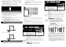
2.3 External wiring
PT100
PT100
CH1
CH4
1mA
DC/ DC
5V
AG
+15V
-15V
AG
A
G
A
G
24+
24-
FG
I-
L-
L+
FG
I-
L-
L+
Converter
System
Class 3 Grounding
(100 of less)
terminal of
power module
Shielded*1
*2
*3
1mA
Shielded*1
Grounding
Note 1: Use only the wires that are packed
with the temperature sensor (PT
100) for analog input and separate
from other power line or any wire
that may cause noise. Please use
3-wire for PT 100.
Note 2: Terminal FG is grounded for noise
suppression.
Note 3: Please connect
power supply
module terminal and
DVP-04PT-S platinum temperature
sensors module terminal to system
earth ground.
Warning: DO NOT connect wires to the No
Connection ( ) terminals.
2.4 Terminals of analog module
DVP04AD-S DVP02DA-S DVP04PT-S DVP04TC-S DVP06XA-S
V
+
I+
COM
FG
V
+
I+
COM
FG
I+
COM
FG
V
+
I+
COM
FG
V
+
V
+
I+
COM
FG
V
+
I+
COM
FG
L+
L-
FG
FG
I-
L+
L-
I-
L+
L-
FG
FG
I-
L+
L-
I-
L+
L-
SLG
L+
L-
SLG
L+
L-
SLG
L+
L-
SLG
V
+
I+
COM
V
+
I+
COM
I+
COM
V
+
I+
COM
V
+
V
+
I+
COM
V
+
I+
COM
3
STANDARD SPECIFICATIONS
3.1 Function Specifications
Platinum Temperature Module (04PT)
Centigrade (°C) Fahrenheit (°F)
Power supply voltage 24 VDC (20.4VDC~26.4VDC) ( –15%~+10%)
Analog input channel 4 channels per module
Sensors type
3-WIRE PT100Ω 3850 PPM/°C(DIN 43760 JIS C1604-1989)
Current excitation 1 mA
Temperature input range
-200°C~600°C -328°F~1112°F
Digital conversion range K-2000~K6000 K-3280~K11120
Resolution
14 bits(0.1°C) 14 bits(0.18°F)
Overall accuracy
±0.5% of full scale of 25°C(77°F), ±1% of full scale during 0~55°C (32~131°F)
Response time
200 ms ×channels
Isolation method Isolation between digital and analog circuitry. There is no isolation between channels.
Digital data format 2’s complement of 16-bit, (13 Significant Bits)
Average function Yes (CR#2~CR#5 may be set and the range is K1~K4096)
Self diagnostic function Yes
Platinum Temperature Module (04PT)
Centigrade (°C) Fahrenheit (°F)
Communication mode (RS-485)
MODBUS ASCII or RTU Mode. Communication baud rate 4800 / 9600 / 19200 / 38400 /
57600 / 115200. For ASCII mode, date format is 7Bits, even, 1 stop bit (7 E 1), while
RTU mode, date format is 8Bits, even, 1 stop bit (8 E 1). RS-485 is disabled when the
DVP04AD-S is connected in series with an MPU.
Connection to a DVP-PLC MPU in series
If DVP04PT-S modules are connected to MPU, the modules are numbered from 0 – 7. 0
is the closest and 7 is the furthest to the MPU. 8 modules is the max and they do not
occupy any digital I/O points of the MPU.
3.2 Other Specification
Maximum Power Consumption 2W at 24 VDC (20.4VDC~28.8VDC) ( -15 % ~ +20 %)
Environment Condition and Wiring Follow the DVP-PLC MPU.
Static Electricity Prevention All places between terminals and ground comply with the spec.
4
CR (Controlled Register)
DVP04PT-S platinum temperature sensors Explanation
CR
No.
RS-485
Parameter
address
Latched Register name b15 b14 b13 b12 b11 b10 b9 b8 b7 b6 b5 b4 b3 b2 b1 b0
#0
H 4064
○
R Model type System used, data length is 8bits (b7~b0). DVP-04PT model code = H 8A
#1 Reserved
#2
H 4066
○
R/W CH1 average number
#3
H 4067
○
R/W CH2 average number
#4
H 4068
○
R/W CH3 average number
#5
H 4069
○
R/W CH4 average number
Number piece of readings used for the calculation of “average” temperature on
channels CH1~CH4.
Setting range is K1~K4096 and factory setting is K10.
#6
H 406A
╳
R
CH1 average degrees(°C)
#7
H 406B
╳
R
CH2 average degrees(°C)
#8
H 406C
╳
R
CH3 average degrees(°C)
#9
H 406D
╳
R
CH4 average degrees(°C)
Average degrees for channels CH1~CH4. (unit: 0.1 degrees C)
#10~ #11 Reserved
#12
H 4070
╳
R
CH1 average degrees(°F)
#13
H 4071
╳
R
CH2 average degrees(°F)
#14
H 4072
╳
R
CH3 average degrees(°F)
#15
H 4073
╳
R
CH4 average degrees(°F)
Average degrees for channels CH1~CH4. (unit: 0.1 degrees F)
#16~ #17 Reserved
#18 H 4076
╳
R
Present temperature of
CH1 (°C)
#19 H 4077
╳
R
Present temperature of
CH2 (°C)
#20 H 4078
╳
R
Present temperature of
CH3 (°C)
#21 H 4079
╳
R
Present temperature of
CH4 (°C)
Present temperature of channels CH1~CH4. (unit: 0.1 degrees C)
#22~ #23 Reserved
#24 H 407C
╳
R
Present temperature of
CH1 (°F)
#25 H 407D
╳
R
Present temperature of
CH2 (°F)
#26 H 407E
╳
R
Present temperature of
CH3 (°F)
#27 H 407F
╳
R
Present temperature of
CH4 (°F)
Present temperature of channels CH1~CH4. (unit: 0.1degrees F)
#28~ #29 Reserved
#30 H 4082
╳
R Error status Data register stores the error status. Refer to the fault code chart for details.
#31 H 4083
○
R/W Communication address
setting
RS-485 communication address.
Setting range is 01~255 and factory setting is K1
#32 H 4084
○
R/W Communication baud rate
setting
Communication baud rate (4800, 9600, 19200, 38400, 57600 and 115200 bps).
b0: 4800 bps (bit/sec).
b1: 9600 bps (bit/sec). (factory setting)
b2: 19200 bps (bit/sec).
b3: 38400 bps (bit/sec).
b4: 57600 bps (bit/sec).
b5: 115200 bps (bit/sec).
b6~b13: Reserved.
b14: switch between low bit and high bit of CRC code (RTU mode only)
b15: RTU mode.
b15 b14 b13 b12 b11 b10 b9 b8 b7 b6 b5 b4 b3 b2 b1 b0
Definition of ERR
LED
CH4 CH3 CH2 CH1
#33 H 4085
○
R/W Reset to factory setting
Example: Setting of CH1
1. b0 Reserved
2. b1 Reserved
3. b2: Set to 1 and PLC will be reset to factory settings.
Definition of ERR LED: b12~b15=1111(factory settings)
1. b12 corresponds to CH1: when b12=1, scale exceeds the range or external
contact has no connection, ERR LED flashes.
2. b13 corresponds to CH2: when b13=1, scale exceeds the range or external
contact has no connection, ERR LED flashes.
3. b14 corresponds to CH3: when b14=1, scale exceeds the range or external
contact has no connection, ERR LED flashes.
4. b15 corresponds to CH4: when b15=1, scale exceeds the range or external
contact has no connection, ERR LED flashes.
#34 H 4086
○
R Software version Display the software version in hexadecimal. Example: H 010A = version 1.0A.
#35~#48 System used
○ means latched.
╳ means not latched.
R means read data by using FROM command or RS-485.
W means write data by using TO command or RS-485.
Explanation:
1. CR#0: PLC model type.
2. CR#1, CR#10, CR#11, CR#16, CR#17, CR#22, CR#23, CR#28, CR#29 are reserved.
3. CR#2 ~ CR#5: Used to set the number piece of input readings used for the calculation of average
temperature. The available range is K1~K4096 and factory setting is K10.