


4. CR#6 to CR#9: The average temperature (°C). Temperature is calculated by averaging multiple
pieces temperature readings. Example: If CR#2 is 10, the temperature in CR#6 will be the
average of the last 10 readings on CH1.
5. CR#12 to CR#15: The average temperature (
°F). Temperature is calculated by averaging multiple
pieces temperature readings. Example: If CR#2 is 10, the temperature in CR#12 will be the
average of the last 10 readings on CH1.
6. CR#18 ~ CR#21: display the present temperature (
°C) of CH1~CH4 input signal.
7. CR#24 ~ CR#27: display the present temperature (
°F) of CH1~CH4 input signal.
8. CR#30 is the fault code register. Refer to the chart below.
Fault description
Content
b15~b8 b7 b6 b5 b4 b3 b2 b1 b0
Power source abnormal K1(H1) 0 0 0 0 0 0 0 1
Analog input value error K2(H2) 0 0 0 0 0 0 1 0
Setting mode error K4(H4) 0 0 0 0 0 1 0 0
Offset/Gain error K8(H8) 0 0 0 0 1 0 0 0
Hardware malfunction K16(H10) 0 0 0 1 0 0 0 0
Digital range error K32(H20) 0 0 1 0 0 0 0 0
Average times setting error K64(H40) 0 1 0 0 0 0 0 0
Command error K128(H80)
Reserved
1 0 0 0 0 0 0 0
Note: Each fault code will have corresponding bit (b0~b7). Two or more faults may happen at the same time. 0 means normal and
1 means having fault.
9. CR#31: RS-485 communication address. Setting range is 01~255 and factory setting is K1.
10. CR#32: RS-485 communication baud rate: 4800, 9600, 19200, 38400, 57600 and 115200.
b0:4800bps, b1:9600bps (factory setting), b2:19200bps, b3:38400 bps, b4:57600 bps, b5:115200
bps, b6~b13: Reserved, b14: switch between low bit and high bit of CRC code (RTU mode only) b15:
ASCII or RTU mode.
Communication format for ASCII mode is 7Bit, even bit, 1 stop bit (7 E 1), while
RTU mode is 8Bit, even bit, 1 stop bit (8 E 1).
11. CR#33: b0~b11: Used to reset the settings of CH1~CH4 to factory defaults.
b12~b15: definition of ERR LED, factory setting is b12~b15=1111.
12. CR#34: software version.
13. CR#35~ CR#48: Reserved for internal system use.
14. The corresponding parameters address H4064~H4095 of CR#0~CR#48 are provided for users to
read/write data via RS-485 communication.
A. Communication baud rate: 4800, 9600, 19200, 38400, 57600, 115200 bps.
B. Communication format: ASCII mode is 7Bit, even bit, 1 stop bit (7 E 1). Communication
format of RTU mode is 8Bit, even bit, 1 stop bit (8 E 1).
C. Function code: 03H—read data from register. 06H—write one WORD to register. 10H—write
multiple WORD to registers.
5
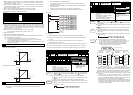
Temperature/Digital Characteristic Curve
Temperature mode: (Centigrade)
+6000
+3000
-2000
+600-200
Digital Output
Temperature Input
C C
Temperature mode: (Fahrenheit)
+11120
+5560
-3280
+1112
-328
Digital Output
Temperature Input
F F
6
Initial PLC Start-up
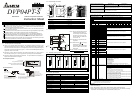
LED display:
1. Upon power-up, the ERROR LED will light for 0.5 seconds the POWER LED will light
continuously.
2. No errors: POWER LED on and ERROR LED off.
Low Voltage error (lower than 19.5V), ERROR LED will blink continuously till the power
supply goes above 19.5V.
3. DVP04-PT connected to PLC MPU in series = RUN LED on MPU will be lit and A/D LED or
D/A LED should blink.
4. After receiving the first RS-485 command, the A/D LED or D/A LED will blink.
5. If the input or output exceeds the upper or lower bounds, the ERROR LED will blink.
Example:
M1000
FROM K0
= H8A D0
TO K0
FROM K0
FROM K0
FROM K0
FROM K0
END
M1002
Explanation:
Read the model type of extension module K0 (should be H8A for DVP04PT-S model type).
Number of piece, saved in D10~D13, used to calculate the average temperature reading (
°C) of
CH1~CH4
For DVP04PT-S model. Read the average temperature (
°C) of CH1~CH4 (4 data) from
CR#6~CR#9 and save it to D20~D23.
Read the average temperature
(°F) of CH1~CH4 from CR#12~CR#15 and save it to D24~D27.
Read the present temperature (
°C) of CH1~CH4 from CR#18~CR#21 and save it to D30~D33.
Read the present temperature
(°F) of CH1~CH4 from CR#24~CR#27 and save it to D34~D37.
7
Related Instructions Explanation
API
Adaptive model
ES EP EH
78
D
FROM
P
Special module CR
data read out
Bit device Word device
X Y M S K H KnX KnY KnM KnS T C D E F
m
1
¼ ¼
m
2
¼ ¼
D
¼ ¼ ¼ ¼ ¼ ¼ ¼ ¼
n
¼ ¼
Note: The usage range of operand m
1
is 0~7.
The usage range of operand m
2
: ES/EP: 0-48,
EH: 0-254.
The usage range of operand n: ES/EP: n=
1~(49-m2), EH: 1~(255-m2).
ES series model doesn’t support the pulse
execution command (FROMP, DFROMP).
16-bit command (9 STEPS)
FROM
Continuous
execution
FROMP
Pulse
execution
32-bit command (17 STEPS)
DFROM
Continuous
execution
DFROMP
Pulse
execution
Flag: When M1083 On, it allows to
enable interrupt during
FROM/TO. Refer to the
below for detail.
Command
Explanation
: the module number you are probing. : the number of Controlled Registers
to be read.
: the data register location for storing data. : the number of CRs
to read at one time.
DVP-series PLC uses this command to read CR data of each special module.
: When assigning bit operand, K1~K4 are used for 16-bit and K5~K8 are used
for 32-bit.
Please refer the footnote below for the calculation of special module number.
Program
Example
Read the content of CR#24 and CR#25 of module#0 and save it to D0 and D1 when
n=2.
Command will be executed when X0=ON. Nothing happen if X0=OFF, the stored
data will have no change.
X0
FROM K0
API
Adaptive model
ES EP EH
79
D
TO
P
Special module CR
data write
Bit device Word device
X Y M S K H KnX KnY KnM KnS T C D E F
m
1
¼ ¼
m
2
¼ ¼
S
¼ ¼ ¼ ¼ ¼ ¼ ¼ ¼ ¼ ¼ ¼
n
¼ ¼
Note: The usage range of operand m
1
is 0~7.
The usage range of operand m
2
: ES/EP: 0-48,
EH: 0-254.
The usage range of operand n: ES/EP: n=
1~(49-m2), EH: 1~(255-m2).
For ES series, it doesn’t support the pulse
execution command (TOP, DTOP)
16-bit command (9 STEPS)
TO
Continuous
execution
TOP
Pulse
execution
32-bit command (17 STEPS)
DTO
Continuous
execution
DTOP
Pulse
execution
Flag: When M1083 On, it allows
to enable interrupt during
FROM/TO. Refer to the below for
detail.
Command
Explanation
: the module number you are probing. : the number of Controlled
Registers that will be written to.
: the data to write. : the number of CR to
write to one time.
DVP-series PLC uses this command to write data to Controlled Registers of special
modules.
: When assign bit operand, K1~K4 are used for 16-bit and K5~K8 are used
for 32-bit.
Program
Example
Using 32-bit command DTO. The program will write D11 and D10 to CR#3 and
CR#2 of special module#0. DTO allows only one group data to be written at one
time when n=1.
Command is executed when X0=ON. Nothing happen if X0=OFF, the stored data
will have no change.
X0
DTO K0
Footnote
The rules for adding multiple special modules to a Main Processing Unit:
m1: The maximum number of special modules attached to an MPU is 8. The
module closest to the MPU is 0 and the furthest module to the MPU is 7.
m2: The number of Controlled Registers (CR) built in is 49. (#0~#48).
FROM/TO command read/write one CR at a time, while DFROM/DTO
command read/write two CR at a time. Example below:
Upper 16-bit Lower 16-bit
Assigned CR numer
(Access16-bit if n=2, or 32-bit if n=1. Same controlled registers are accessed).
D0
D1
D2
D3
D4
D5
D0
D1
D2
D3
D4
D5
CR#5
CR#6
CR#7
CR#8
CR#9
CR#10
CR#5
CR#6
CR#7
CR#8
CR#9
CR#10
Assigned
Equipment
Assigned
CR
Assigned
Equipment
Assigned
CR
16-bit command when n=6 32-bit command when n=3
In ES series models, flag M1083 is not provided. When FROM/TO command is
executed, all interrupts (including external or internal interrupt subroutines) will be
disabled. All interrupts will be executed after FROM/TO command is completed.
Besides, FROM/TO command also can be executed in the interrupt subroutine.
The function of the flag M1083 (FROM/TO mode exchange) provided in EP/EH
series models:
1. When M1083=Off, all interrupts (including external or internal interrupt
subroutines) will be disabled when FROM/TO command is executed. The
Interrupts will resumed after FROM/TO command complete. Please be advised
FROM/TO command can be executed in the interrupt subroutine.
2. When M1083=On, if an interrupt enable occurs while FROM/TO command are
executing, the interrupt FROM/TO command will be blocked till the requested
interrupt finish. Unlike M1080 off situation, FROM/TO command cannot be
executed in the interrupt subroutine.