


http://www.delta.com.tw/industrialautomation/
DVP04TC-S
Thermocouple Sensors
Instruction Sheet
1 WARNING
Always read this instruction thoroughly before using the DVP04TC-S.
Make sure that power is OFF before wiring.
This is an OPEN TYPE PLC. The PLC should be kept in an enclosure away from airborne dust,
humidity, electric shock risk and vibration. Also, it is equipped with protective methods such as
some special tools or keys to open the enclosure, in order to prevent hazard to users or damage
the PLC.
Do NOT connect the AC main circuit power supply to any of the input/output terminals, or it may
damage the PLC. Check all the wiring prior to power up.
Do NOT touch internal circuit within 1 minute after power is OFF.
Make sure that the DVP04TC-S is properly grounded , to avoid any electromagnetic noise.
2 INTRODUCTION
2.1 Model Explanation and Peripherals
Thank you for choosing DELTA’s DVP Series PLC. The DVP04TC-S allows the connection of
four thermocouple sensors (Type J/K). The DVP04TC-S series can read/write the data by using
instructions FROM / TO via DVP-PLC SS/SA/SX/SC MPU program. There are 49 CR (Control
Register) in each module and 16 bits for each register.
DVP04TC-S thermocouple sensor can update software version by RS-485. Power supply and
main processing units are sold separately.
The DVP04TC-S works with both Centigrade and Fahrenheit. The input resolution for
Centigrade is 0.1 degrees and for Fahrenheit is 0.18 degrees.
Nameplate Explanation
PLC model
Input power Supply Spec.
Analog Input /Output Module Spec.
Barcode, series and version
MODEL
:
POWER INPUT
:
THERMOCOUPLES
:
04TC-S0T5020001VX.X
24Vdc 2W
MADE IN XXXXXX
RESOLUTION
:
14 BITS
TYPE J , K
Model Explanation
Serial Number
Model
S: for SS/SA series MPU
XA: Analog input/output mixed module
Product Series
Input + Output points
Model type
AD: Analog input module
DA: Analog output module
PT: Platinum temperature sensors (PT-100)
TC: Thermocouple sensors (Type J/K)
Production series
Production week
Production year (2005)
Production place (Taoyuan)
Serial number of version
Production Model
RT: Resistor Thermocouple(NTC)
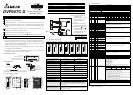
2.2 Product Profile and Outline
90.00
4.00
3.00
25.20
1
2
3
4
60.00
5
6
7
8
9
3
10
L+
L-
SLD
C
H
1
C
H
2
C
H
3
C
H
4
11
12
13
3.4
90.00
60.00
3.00
14
●
L+
L-
L+
L-
L+
L-
SLD
SLD
SLD
●
●
●
●
●
Unit: mm
1. Status indicator (Power, RUN and ERROR) 8. Extension port
2. Model Number 9. Extension Clip
3. DIN rail clip 10. DIN rail location (35mm)
4. I/O terminals 11. RS-485 Communication port
5. I/O point indicator 12. Extension Clip
6. Extension hole of the extension unit mounting
pins
13. DC Power input
7. Specification Label 14. Extension port
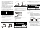
2.3 External wiring
CH1
CH4
DC/ DC
5V
AG
+15V
-15V
AG
24+
24-
SLD
L-
L+
SLD
L-
L+
Converter
System
Class 3 Grounding
(100 of less)
terminal of
power module
Shielded*1
*2
*3
Shielded*1
Grounding
Thermocouple
+
-
100
MUX
Cold-junction
Compensation
Thermocouple
+
-
Note 1: Use only the wires that are
supplied with your
thermocouple sensor. Tighten
PLC terminal screws to a
torque of 1.95 kg-cm (1.7
in-lbs).
Note 2: Terminal SLD is a grounding
location for noise suppression.
Note 3: Please connect
terminal of
power supply module and
terminal of DVP04TC-S
thermocouple sensors module
to system earth ground.
Warning: DO NOT connect wires to the
No Connection ( ) terminals.
Use copper conductor only,
60℃
2.4 Terminals of analog module
DVP04AD-S DVP02DA-S DVP04DA-S DVP04PT-S DVP04TC-S DVP06XA-S DVP08RT-S
V
+
I+
COM
FG
V
+
I+
COM
FG
I+
COM
FG
V
+
I+
COM
FG
V
+
V
+
I+
COM
FG
V
+
I+
COM
FG
V
+
I+
COM
FG
V
+
I+
COM
FG
I+
COM
FG
V
+
I+
COM
FG
V
+
L+
L-
FG
FG
I-
L+
L-
I-
L+
L-
FG
FG
I-
L+
L-
I-
L+
L-
SLG
L+
L-
SLG
L+
L-
SLG
L+
L-
SLG
V
+
I+
COM
V
+
I+
COM
I+
COM
V
+
I+
COM
V
+
V
+
I+
COM
V
+
I+
COM
L+
L-
L-
L-
L+
L+
L-
L+
L+
L-
L-
L-
L+
L+
L-
L+
3 STANDARD SPECIFICATIONS
3.1 Function Specifications
Platinum Temperature Module (04TC)
Centigrade (°C)
Fahrenheit (°F)
Power Supply Voltage 24 VDC(20.4VDC~28.8VDC) ( –15%~+20%)
Analog Input Channel 4 channels per module
Sensors Type J-type or K-type thermocouple
Temperature Input Range
J-type: -100°C~700°C
K-type: -100°C~1000°C
J-type: -148°F~1292°F
K-type: -148°F~1832°F
Digital Conversion Range
J-type: K-1000~K7000
K-type: K-1000~K10000
J-type: K-3280~K12920
K-type: K-1480~K18320
Resolution
14 bits(0.1°C) 14 bits(0.18°F)
Overall Accuracy
±0.5% of full scale of 25°C(77°F), ±1% of full scale during 0~55°C
(32~131°F)
Response Time
250 ms × channels
Isolation Method
Isolation between digital and analog circuitry. There is no isolation between
channels.
Digital Data Format 2’s complement of 16-bit, (13 Significant Bits)
Average Function Yes (CR#2~CR#5 may be set and the range is K1~K4096)
Self Diagnostic Function Yes
Communication Mode (RS-485)
MODBUS ASCII/RTU Mode. Communication baud rate of 4800 / 9600 /
19200 / 38400 / 57600 / 115200. For ASCII mode, date format is 7Bits,
even, 1 stop bit (7 E 1). For RTU mode, date format is 8Bits, even, 1 stop
bit (8 E 1). The RS-485 is disabled when the DVP04TC-S is connected in
series to an MPU.
Connection to a DVP-PLC MPU in
Series
When DVP04TC-S modules are connected to an MPU, the modules are
numbered from 0 – 7. 0 is the closest to the MPU and 7 is the farthest. The
Maximum number of modules is 8 modules and they do not occupy any
digital I/O points of the MPU.
3.2 Other Specification
Power Specification
Maximum Power Consumption 2W at 24 VDC (20.4VDC~28.8VDC) ( -15 % ~ +20 %)
Environment Condition
Environment Condition Follow the DVP-PLC MPU.
Static Electricity Prevention All places between terminals and ground comply with the spec.
4 CR (Controlled Register)
DVP04TC-S platinum temperature sensors Explanation
CR
No.
RS-485
Parameter
address
Latched Register name b15 b14 b13 b12 b11 b10 b9 b8 b7 b6 b5 b4 b3 b2 b1 b0
#0
H 4096
○
R Model type System used, DVP04TC-S model code = H 8B
Reserved CH4 CH3 CH2 CH1
#1
H 4097
○
R/W Thermocouple type
Example: Setting of CH1
1. b0: set 0 to use J-type and set 1 to use K-type
2. b1: Reserved.
3. b2: Reserved.
#2
H 4098
○
R/W CH1 average number
#3
H 4099
○
R/W CH2 average number
#4
H 409A
○
R/W CH3 average number
#5
H 409B
○
R/W CH4 average number
The number of readings used for “average” temperature on channels CH1~CH4.
Setting range is K1~K4096 and factory setting is K10.
#6
H 409C
╳
R
CH1 average degrees(°C)
#7
H 409D
╳
R
CH2 average degrees(°C)
#8
H 409E
╳
R
CH3 average degrees(°C)
#9
H 409F
╳
R
CH4 average degrees(°C)
Average degrees for channels CH1~CH4. (unit: 0.1 degrees C)
#10
H 40A2
╳
R
CH1 average degrees(°F)
#11
H 40A3
╳
R
CH2 average degrees(°F)
#12
H 40A4
╳
R
CH3 average degrees(°F)
#13
H 40A5
╳
R
CH4 average degrees(°F)
Average degrees for channels CH1~CH4. (unit: 0.1 degrees F)
#14
H 40A8
╳
R
Present temperature of
CH1 (°C)
#15
H 40A9
╳
R
Present temperature of
CH2 (°C)
#16
H 40AA
╳
R
Present temperature of
CH3 (°C)
#17
H 40AB
╳
R
Present temperature of
CH4 (°C)
Present temperature of channels CH1~CH4. (unit: 0.1 degrees C)
#18 Reserved
#19
H 40AE
╳
R
Present temperature of
CH1 (°F)
#20
H 40AF
╳
R
Present temperature of
CH2 (°F)
#21
H 40B0
╳
R
Present temperature of
CH3 (°F)
#22
H 40B1
╳
R
Present temperature of
CH4 (°F)
Present temperature of channels CH1~CH4. (unit: 0.1degrees F)
#23 Reserved
#24
H 40AE
○
R
CH1 OFFSET Value
#25
H 40AF
○
R
CH2 OFFSET Value
#26
H 40B0
○
R
CH3 OFFSET Value
#27
H 40B1
○
R
CH4 OFFSET Value
Adjust offset value of channels CH1~CH4. The range is -1000~+1000 and
factory setting is K0. (unit: 0.1 degrees C)
#28~#29 Reserved
#30
H 40B4
╳
R Error status Data register stores the error status, refer to fault code chart for details.
#31
H 40B5
○
R/W Communication address
setting
RS-485 communication address.
Setting range is 01~255 and factory setting is K1
#32
H 40B6
○
R/W Communication baud rate
setting
Communication baud rate (4800, 9600, 19200, 38400, 57600 and 115200 bps).
b0: 4800 bps (bit/sec).
b1: 9600 bps (bit/sec). (factory setting)
b2: 19200 bps (bit/sec).
b3: 38400 bps (bit/sec).
b4: 57600 bps (bit/sec).
b5: 115200 bps (bit/sec).
b6~b13: Reserved.
b14: switch between low bit and high bit of CRC code (only for RTU mode)
b15: RTU mode.
b15 b14 b13 b12 b11 b10 b9 b8 b7 b6 b5 b4 b3 b2 b1 b0
Definition of ERR
LED
CH4 CH3 CH2 CH1
#33
H 40B7
○
R/W Reset to factory setting
Example: Setting of CH1
1. b0 Reserved
2. b1 Reserved
3. b2: Set to 1 and PLC will be reset to factory settings.
Definition of ERR LED: b12~b15=1111(factory settings)
1. b12 corresponds to CH1: when b12=1, scale exceeds the range or external
contact has no connection, ERR LED flashes.
2. b13 corresponds to CH2: when b13=1, scale exceeds the range or external
contact has no connection, ERR LED flashes.
3. b14 corresponds to CH3: when b14=1, scale exceeds the range or external
contact has no connection, ERR LED flashes.
4. b15 corresponds to CH4: when b15=1, scale exceeds the range or external
contact has no connection, ERR LED flashes.
#34
H 40B4
○
R Software version Display software version in hexadecimal. Example: H 010A = version 1.0A.
#35~#48 System used
○ means latched.
╳ means not latched.
R means can read data by using FROM instruction or RS-485.
W means can write data by using TO instruction or RS-485.
Explanation:
1. CR#0: The PLC model type.