


2. CR#1: Used to set the working mode of four channels (CH1~CH4). There are 2 modes (J-type
and K-type) for each channel and can be set individually. For example, If you want to set
CH1~CH4 as following: CH1: mode 0 (b2~b0=000), CH2: mode 1(b5~b3=001), CH3: mode
0(b8~b6=000) and CH4: mode 1(b11~b9=001), you should set CR#1 to H0208. The higher
bits (b12~b15) will be reserved and the factory setting is H0000.
3. CR#2 ~ CR#5: Used to set the times of input readings for the average temperature calculation.
The available range is K1~K4096 and factory setting is K10. (Note: When PLC sets average
times via TO/DTO instructions, please use rising-edge/falling-edge detection instruction (such
as LDP and LDF) to get correct average times.)
4. CR#6 ~ CR#9: The average temperature (°C). The average temperature is calculated from
multiple temperature readings. Example: If CR#2 is 10, the temperature in CR#6 will be the
average of the last 10 readings in CH1.
5. CR#10 ~ CR#13: The average temperature (°F). The average temperature is calculated from
multiple temperature readings. Example: If CR#2 is 10, the temperature in CR#12 will be the
average of the last 10 readings in CH1.
6. CR#14 ~ CR#17: display present temperature (°C) of CH1~CH4 input signal.
7. CR#18, CR#23, CR#28, CR#29 are reserved.
8. CR#19 ~ CR#22: display present temperature (°F) of CH1~CH4 input signal.
9. CR#24 ~ CR#27: display offset value of channels CH1~CH4. The range is -1000~+1000 and
unit is 0.1 degrees C. The definition of OFFSET is Actual temperature = temperature
measured by DVP04TC-S – OFFSET value.
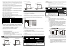
10. CR#30 is a fault code register. Refer to the following chart.
Fault description Content b15~b8 b7 b6 b5 b4 b3 b2 b1 b0
Power source abnormal K1(H1) 0 0 0 0 0 0 0 1
Analog input value error K2(H2) 0 0 0 0 0 0 1 0
Setting mode error K4(H4) 0 0 0 0 0 1 0 0
Offset/Gain error K8(H8) 0 0 0 0 1 0 0 0
Hardware malfunction K16(H10) 0 0 0 1 0 0 0 0
Digital range error K32(H20) 0 0 1 0 0 0 0 0
Average times setting error K64(H40) 0 1 0 0 0 0 0 0
Instruction error K128(H80)
Reserved
1 0 0 0 0 0 0 0
Note: Each fault code will have corresponding bit (b0~b7). Two or more faults may happen at the same time. 0
means normal and 1 means fault occurs.
11. CR#31: RS-485 communication address. Setting range is 01~255 and factory setting is K1.
12. CR#32: RS-485 communication baud rate: 4800, 9600, 19200, 38400, 57600 and 115200.
b0:4800bps, b1:9600bps (factory setting), b2:19200bps, b3:38400 bps, b4:57600 bps,
b5:115200 bps, b6~b13: Reserved, b14: switch between low bit and high bit of CRC code
(only for RTU mode), b15: ASCII / RTU mode. For ASCII mode, date format is 7Bits, even, 1
stop bit (7 E 1). For RTU mode, date format is 8Bits, even, 1 stop bit (8 E 1).
13. CR#33: Used to reset the settings of CR registers to factory settings.
14. CR#34: software version.
15. CR#35~ CR#48: Reserved for internal system use.
16. The corresponding parameters address H 4096~H 40C7 of CR#0~CR#48 may provide users
to read/write data via RS-485 communication.
a. Communication baud rate: 4800, 9600, 19200, 38400, 57600, 115200 bps.
b. Communication format: ASCII mode is 7Bit, even bit, 1 stop bit (7 E 1). Communication
format of RTU mode is 8Bit, even bit, 1 stop bit (8 E 1).
c. Function code: 03H—read data from register. 06H—write a WORD into register.
10H—write many WORDs into register.
5 Temperature/Digital Characteristic Curve
Temperature mode: (Centigrade)
J-type thermocouple
+7000
-1000
+700-100
C
C
Digital output
Temperature
input
K-type thermocouple
Digital outpu
t
Temperature
input
+10000
-1000
+1000-100
C
C
Temperature mode: (Fahrenheit)
J-type thermocouple
Digital output
Temperature
input
+12920
-1480
+1292
-148
F
F
K-type thermocouple
Digital output
Temperature
input
+18320
-1480
+1832
-148
F
F
6 Initial PLC Start-up
LED display:
1. Upon power-up, the ERROR LED will light for 0.5 seconds the POWER LED will light continuously.
2. No errors= POWER LED on and ERROR LED off.
Low Voltage error (lower than 19.5V), ERROR LED will blink continuously till the power supply
rises above 19.5V.
3. DVP04TC-S connected to PLC MPU in series = RUN LED on MPU will be lit and A/D LED or D/A
LED should blink.
4. After receiving the first RS-485 instruction the A/D LED or D/A LED will blink.
5. If the input or output exceeds the upper or lower bounds, then the ERROR LED will blink.
Example:
M1000
FROM K0
= H8B D0
TO K0
FROM K0
FROM K0
FROM K0
FROM K0
END
M1002
Explanation:
Reading the model type of extension module K0 (should be H8B for DVP04TC-S model type).
The averaging number for CH1~CH4 will be D10~D13.
If the model type is DVP04TC-S. Reading the average temperature (°C) of CH1~CH4 (4 data)
from CR#6~CR#9 and save them into D20~D23.
Reading the average temperature (°F) of CH1~CH4 (4 data) from CR#10~CR#13 and save them
into D24~D27.
Reading the present temperature (°C) of CH1~CH4 (4 data) from CR#14~CR#17 and save them
into D30~D33.
Reading the present temperature
(°F) of CH1~CH4 (4 data) from CR#19~CR#22 and save them
into D34~D37.
7 Related Instructions Explanation
API
Applicable model
SS SA/SX/SC EH
78
D
FROM
P
Special module CR
data read out
Bit device Word device
X Y M S K H KnX KnY KnM KnS T C D E F
m
1
¼ ¼
m
2
¼ ¼
D ¼ ¼ ¼ ¼ ¼ ¼ ¼ ¼
n ¼ ¼
Note: The usage range of operand m
1
is 0~7.
The usage range of operand m
2
: SS/SA: 0-48, EH:
0-254.
The usage range of operand n: SS/SA: n= 1~(49-m2),
EH: 1~(255-m2).
SS series model doesn’t support pulse execution
instruction (FROMP, DFROMP).
16-bit instruction (9 STEPS)
FROM
Continuous
execution
FROMP
Pulse
execution
32-bit instruction (17 STEPS)
DFROM
Continuous
execution
DFROMP
Pulse
execution
Flag: When M1083=On, it allows to
insert interrupt during FROM/TO.
Refer to following for detail.
Command
Explanation
m1: the number for special module. m2: the number of CR (Control Register) of special
module that will be read. D: the location to save reading data. n: the data number of
reading one time.
DVP-series PLC uses this instruction to read CR data of special module.
D: When assigning bit operand, K1~K4 can be used for 16-bit and K5~K8 can be used
for 32-bit.
Please refer the following footnote for calculationof special module number.
API
Applicable model
SS SA/SX/SC EH
79
D
TO
P
Special module CR
data write in
Bit device Word device
X Y M S K H KnX KnY KnM KnS T C D E F
m
1
¼ ¼
m
2
¼ ¼
S
¼ ¼ ¼ ¼ ¼ ¼ ¼ ¼ ¼ ¼ ¼
n
¼ ¼
Note: The usage range of operand m
1
is 0~7.
The usage range of operand m
2
: SS/SA: 0-48, EH:
0-254.
The usage range of operand n: SS/SA n= 1~(49-m2),
EH: 1~(255-m2).
For SS series, it doesn’t support pulse execution
instruction (TOP, DTOP)
16-bit instruction (9 STEPS)
TO
Continuous
execution
TOP
Pulse
execution
32-bit instruction (17 STEPS)
DTO
Continuous
execution
DTOP
Pulse
execution
Flag: When M1083=On, it allows
to insert interrupt during
FROM/TO.
Refer to following for detail.
Command
Explanation
m1: the number of special module. m2: the number of CR (Control Register) of special
module that will be wrote in. S: the data to write in CR. n: the data number to write in
one time.
DVP-series PLC uses this instruction to write data into CR of special module.
S: When assigning bit operand, K1~K4 can be used for 16-bit and K5~K8 can be used
for 32-bit.
Footnote
The rule of instruction operand:
m1: arrangement number of special module. The number of special module that
connects to PLC MPU. The numbering order of special module from the near to
the distant of MPU is from 0 to 7. The maximum is 8 special modules and won’t
occupy I/O point.
m2: the number of CR. Built in 16-bit of 49 groups memory of special module is
called CR (Control Register). The number of CR uses decimal digital (#0~#48). All
running status and setting values of special module has included.
If using FROM/TO instruction, the unit of read/write of CR is one number for one
time. If using DFROM/DTO instruction, the unit of read/write of CR is two numbers
in one time.
CR #10 CR #9
Upper 16-bit
Lower 16-bit
Specified CR number
The number of transmission groups n. The meaning of n=2 of 16-bit instruction
and n=1 of 32-bit are the same.
D0
D1
D2
D3
D4
D5
CR #5
CR #6
CR #7
CR #8
CR #9
CR #10
D0
D1
D2
D3
D4
D5
CR #5
CR #6
CR #7
CR #8
CR #9
CR #10
Specified device
Specified C
R
Specified device
Specified CR
16-bit command when n=6
32-bit command when n=3
In SS series models, flag M1083 is not provided. When FROM/TO instruction is
executed, all interrupts (including external or internal interrupt subroutines) will be
disabled. All interrupts will be executed after FROM/TO instruction is completed.
Besides, FROM/TO instruction also can be executed in the interrupt subroutine.
The function of the flag M1083 (FROM/TO mode exchange) provided in SA
/
EH series
models:
1. When M1083=Off, FROM/TO instruction is executed, all interrupts (including
external or internal interrupt subroutines) will be disabled. All interrupts will be
executed after FROM/TO instruction is completed. Besides, FROM/TO
instruction also can be executed in the interrupt subroutine.
2. When M1083=On, if an interrupt occurs while FROM/TO instruction has been
programmed, FROM/TO instruction will be interruptted to execute the
interrupt. However, FROM/TO instruction cannot be executed in the interrupt
subroutine.