


DVPDU-01 Digital Setup Display
Instruction Sheet
1 WARNING
Please power down the MPU of the
PLC prior to install the DU-01, which
is connected via a high-density
connector. Also please read the
figures on the right for operation
correctly to prevent damage.
2 INTRODUCTION
DU-01 Digital Setup Display has two operation modes, TS-01 and
TC-01. The mode selection switch locates at the back of the
DU-01. Factory setting is TS-01 mode. The current operation
mode will be displayed every time when power up.
TS-01
TC-01
Back of the DU-01
1. In TS-01
mode, DU-01 (specified as TS-01 hereof) has the following functions:
• Read/Write both the internal devices of PLC (e.g. perpetual calendar, bit devices (X, Y, M, S)
and word devices (T, C, D)) and the Control Register (CR) inside the extension units.
• Support the read/write 32-bit data register.
• Set Start-up display and power save mode.
• Monitor the devices.
• If connect the accessory cable to ES-series without perpetual calendar, the Time Display will
start from 00-00-00 calculated by the microprocessor of DU-01 (timing error may occur).
• Give RUN-STOP command to PLC.
2. In TC-01
mode, DU-01 (specified as TC-01 hereof) has the following functions for DVP all series:
• Read/write the program P, data register D and file register F from PLC.
• Copy program and data.
• Support the PLC password protection.
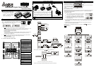
Overview of the Product - Names of Parts
1
P: program area indication
(TC-01)
2 W: write (WR) indication (TC-01)
3 R: read (RD) indication (TC-01)
4 “In communication” indication
5
D: Data Register indication
(TC-01)
6
F: File Register indication
(TC-01)
7
CR: Control Register indication
(Extension Module)
8 ER: Error message display
9 Display Area
10
Enter button
indication
11
K (Decimal), H (Hexadecimal)
indication
12
Contacts & coils of timer /
counter indications
13
Word devices T, C, D, DD
(32-bit)
indication
14 Bit devices X, Y, M, S indication
15 Digit backspace / Run (TC-01)
16 Back to previous status
17 Enter number or select device
18 Confirm
ESC
OK
4
3
2
1 5
6
7
8
9
DU-01
19 Enter number or select device
3 INSTALLATION & WIRING
1. Direct mounting to the expansion slot in the MPU of
the EP/EH series
Please power down the PLC MPU prior to install the DU-01,
which is connected via a high-density connector. Also please
refer to the figures above for proper operation. Put the
face-up DU-01 slantly in the extension slot, then push it down
in arrow direction. DO NOT push it down vertically to prevent
damage.
2. Connecting to DVP
series PLC via accessory
cable
(No need to shut down the MPU)
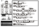
4 TS-01 OPERATION
1. Switch DU-01 to TS-01 mode. (Please see the back of the DU-01)
2. Main Process
OK
ESC
ESC
OK
ESC
ESC
OK
OK
ESC
Time Mode
Press and hold for 3 sec.
Auto Save
Confirm & update time
Operation Mode
Display
Selection
No Save
YY-MM-DD
HH-MM-SS
Device
Selection
Device Selection
X, Y, M, S
T, C, D
CR
DD(32-bit)
OK
OK
OK
OK
OK
OK
OK
ESC
ESC
ESC ESC
ESC
Device
Monitor
Bit
Device
Word
Device
Device confirm
Device confirm
Number Selection
Specify a number
Force On/Off setting
Specified No.
Display
Enter Set Value
Enter a number
Number Selection
Press
to complete entering & return
Monitor status of 8 consecutive
devices from the specified number
Press and hold for 3 sec.
Press and hold for 3 sec.
Press and hold for 3 sec.
Press and hold for 3 sec.
3. Start-up display mode setting (press + buttons simultaneously)
Any mode*
Sleep mode
Monitor
Mode
Press +
Until shows
+
Time & device
content
Sleep mode activated if no button is pressed
within 30 seconds
*Note: not include system operation mode setting
4. Please see the back page for detail information about the process of each mode.
5 TC-01 OPERATION
1. Switch the DU-01 to TC-01
mode (please see the back of
the DU-01), and select RD (to
read P, D and F in the MPU of
PLC) or WR (to write the data
in P, D, F of DU-01 to the MPU
of PLC).
TC-01
Indication of the connected MPU model
Indication of internal data storage model
Note: P: Program, D: Data register, F: File register
2. TC-01 Password Key Setting
Password key setting of TC-01 can be set via WPLSoft. The purpose is to read/write to the key-locked
PLC as long as the password setting matches with the one in PLC. To unlock the password key
setting, please use WPLSoft as well.
a) Password Key Setting
In RD or WR mode, press ESC button and hold for 3 seconds or
more to enter password setting. See the figure on the right:
Open WPLSoft [Setting] [TC-01 password key setting].
Select [Enter TC-01 password key], and operate as instructed.
After setting, display shows the figure on the right. (KEY SET),
then press ESC to exit.
b) TC-01 has password key setting, therefore, only if the PLC has no password protection or with the
same password with TC-01 can process the writing. It also writes the password to the PLC for
added protection.
c) Password key clear (KEY CLR): Same as the operation above. Open WPLSoft, select [TC-01
password key clear], and operate as instructed.
3. Clear P, D, F of TC-01: select the device (P, D or F) to be cleared, press
+ simultaneously,
then press ESC.
4. RD mode description:
RD read mode
P,D,F selection
+
P(Program)
D (Data Register)
F (File Register)
Reading P (Program).
You can press ESC to
pause reading.
Setting reading range.
(default start & end
addresses are latched
area range. User can
re-set it.)
Reading F (file register)
You can press ESC to
pause reading.
Enter start address
Finish reading
Finish reading
Finish reading
Finish reading.
d1EC is the CHKSUM
of writing program
2746 is the CHKSUM
of writing data
Enter end address
Reading processing...
You can press ESC to
pause reading.
Confirm
Device