


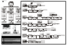

Various process for operation modes under TS-01 mode
System operation
mode setting
Mode selection
On/Off
A
uto Save setting
Time display mode
Sleep mode setting
Fill 0 setting (fill 0 before number or not)
Start-up display setting
(On: activate, Off: deactivate)
(On: not to display 0, Off: display 0)
(On: allow to customize start-up display,
Off: Default time display)
DF
CR ER
R
W
P
+
OK
TCD
DD
ESC
KHXYMS
PLC calendar setting
DF
CR ER
R
W
P
+
OK
TCD
DD
ESC
KHXYMS
Field selection
for setting
Set the contents
Time display mode
Select yy-mm-dd/hh-mm-ss
Confirm & update the time
OK
ESC
confirm device
OK
ERCR
FDPW
K
The right four digits show 8 consecutive
displays/settings that starts from Y10
Move to the
digit to be set
Device status display
Set device's number
Y10 Y11 Y12 Y13
Y14 Y15 Y16 Y17
Y10,Y12,Y15,Y17 are On
(Depends on actual output of the PLC)
Press and hold for 3 sec.until the blinking cursor shows
K
K
X, Y, M, S
Select device
ESC
Move the bit to
desired device's
number
ERCRFDP
W
K
Forced On/Off
setting
ERCRFDPW
Device select mode
OK OK
ESC
The left four digits show device number 's
4. WR mode description:
WR writing mode
P,D,F selection
Device Confirm
+
P (Program) D (Data Register) F (File Register)
Writing to P (Program)
in PLC.
You can press ESC
to pause writing during
TC-01-> PLC.
Setting reading range.
(default start & end
addresses is latched
area range. User can
change it.)
Writing to F
(File Register) in PLC.
You can press ESC
to pause writing during
TC-01->PLC.
Finish writing
Finish writing
Finish writing.
d1EC is the CHKSUM
of writing data.
Finish writing
d1EC is the CHKSUM
of writing data.
Blink alternatively
Start End +
Finish writing
Finish writing.
d1EC is the CHKSUM
of writing data.
6 DIMENSIONS & ACCESSORY
Confirm device
OK
ERCR
FDPW
K
Move to the
digit to be set
Current value
display
Set the number
K
T, C, D, DD
Select device
ESC
ERCR
FD
OK OK
ESC
DD stands for 32-bit data register
(Press and hold for 3 sec.)
Use to switch between K (decimal) / H (hexadecimal) display mode.
For
will light up.
32-bit registers, use to move to display the two left-most digits.
At this time, indicator
Both timer and counter have coils & contacts monitor.
PW
K
ESC
Device select mode
Word device
DU-01
ESC
OK
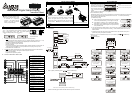
Expansion
COM Port
DVP-PLC COM1
Connecting to
(RS-232 Port)
The accessory cable connects the DU-01 (the extension COM port of figure above) and
DVP-series PLC COM1 (RS-232) port. Therefore, the DU-01 can be connected to ES/SS/EX
or SA/SX models via the cable, as well as direct installation in the extension slot of EP/EH
models.
7 ERROR CODE TABLE
Code Code Explanation & Troubleshooting
Error-00
P-read error. PLC is password-locked while the TC01 has wrong or no password
key. Need unlock the password setting on PLC or set password in TC-01 via WPL.
Error-01
P-write error. PLC is password-locked while the TC01 has wrong or no password
key; or the source model unmatched the destination model.
Error-02
D-read error. Illegitimate read range (read range only available for the general data
registers of each models, not include special D)
Error-03 D-write error. The source model unmatched the destination model.
Error-04 F-read error. ES series does not have file registers.
Error-05 F-write error. The source model unmatched the destination model.
Error-06 PLC is running. Writing to P is not permitted.
Enter Set Value
Move to the digit
to be set
Current value
display
T, C, D, DD
ESC
ERCR
FD
OK
ESC
Enter Set Value mode
PW
K
OK
Device number setting
ERCRFDPW
K
For example:
Display two left-most digits
for 32-bit register.
(Press and hold for 3 sec.)
Enter Set Value & return
to monitor mode
confirm CR
OK
CR number
Specify CR number
K
select device
ESC
ER
CR
FD
OK
Specify the expansion
unit number
Current value
display
ESC
(0,1,2...7)Expansion unit number
32-bit
16-bit
(Press and hold for 3 sec.)
OK
PW
K
Enter Set Value mode
Device select mode
PLC status display
Time display mode
DF
CR ER
R
W
P
+
OK
TCD
DD
ESC
KHX YMS
PLC status switch
Device select mode