


http://www.delta.com.tw/products/plc.asp
DVP-EH
Function Card
Instruction Sheet
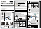
1 WARNING
Always read this manual thoroughly before using Function Extension Card.
This instruction provides electrical specification, function specification, wiring and basic program
design. For detail program design and instruction explanation information refer to PLC Application
Manual (programming).
This is an OPEN-TYPE. When installing, you should turn MPU power off and have static
electricity protection, such as wear antistatic gloves, to avoid damage those components on
function extension card caused by statics.
This instruction is for DVP series function extension card. Please find out your order model in the
following for correct usage.
2
INTRODUCTION
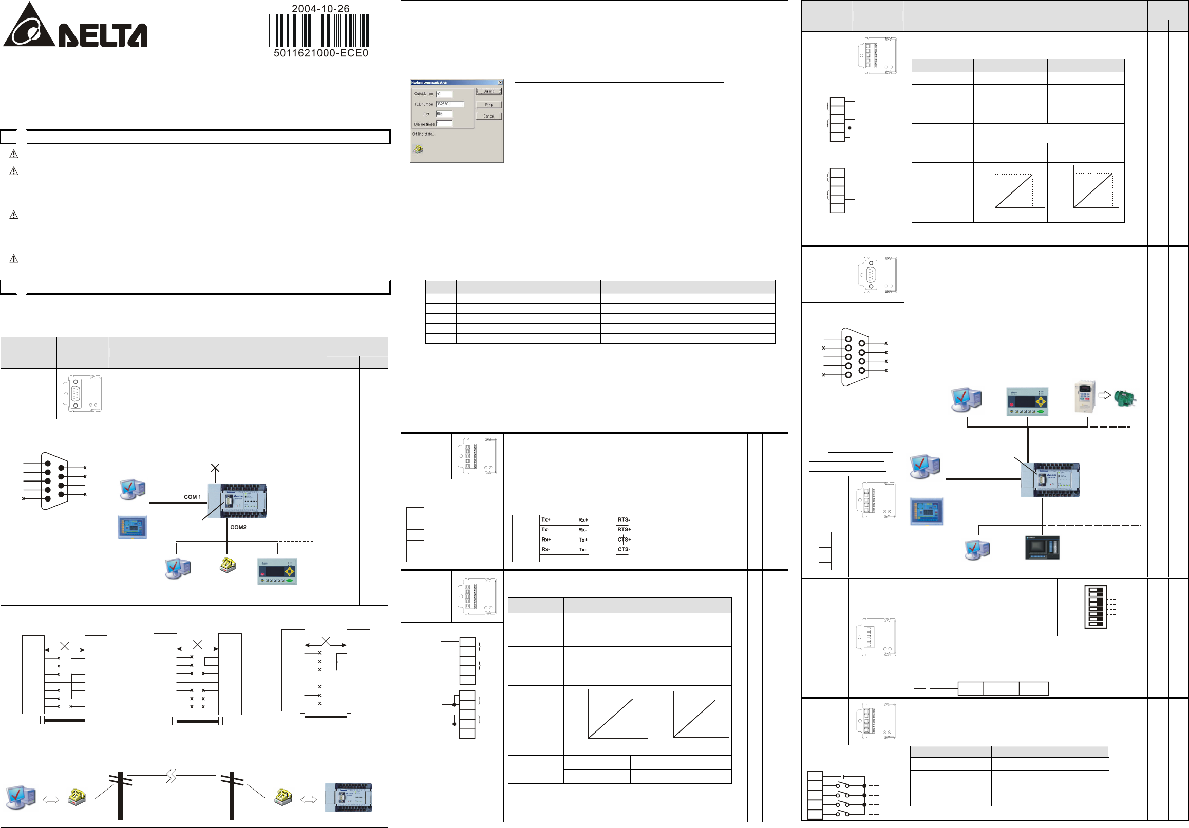
Thank you for choosing DELTA’s PLC extension card of DVP-EP/EH Series. There are analog
input/output card (AI/AO), digital input/output card (DI/DO), extension card for communication port and
memory card. Refer to following table for detail.
Applicable
Model
Model Name Outline Function Explanation
EP EH
DVP-F232
(RS-232 card)
Terminal Layout (DB-9
male)
V. High: high potential, i.e. logic 1
GND
V. High
Tx
Rx
V. High
5
3
2
1
9
8
7
6
4
Note:
Please pay attention for
pin 2 and pin 3 when
connecting this
communication port to
PC or HMI.
MPU built in COM1(RS-232) and COM2(RS-485).
When connecting RS-232 to PC or other peripheral,
such as MODEM, by using COM2, you can use this
extension card. The communication function is the
same as COM2 except communication interface, i.e.
there are Slave mode and Master mode for you to
choose. Note: PLC will set that COM2 is occupied by
RS-232 card and built-in COM2 (RS-232) function will
be invalid after inserting this card. Refer to following for
system connection.
PC
HMI
or
DVP EP/EH MPU
select one deviceMaster/Slave
(RS-232)
extension card for
communication port
DVP-F232 DVP-F422or
MODEM
PC
HMI
RS-485 is invalid
○ ○
Application example for connection in Slave mode
3
2
7
8
6
5
1
4
9
7
8
6
5
1
4
9
3
2
PLC COM2
PC RS-232
serial port
DB-9
FEMALE
DB-9
FEMALE
Tx Tx
Rx Rx
Rl.
GND
S.G.
3
2
7
8
6
5
1
4
9
7
8
6
5
1
4
9
3
2
PLC COM2
DB-9
FEMALE
DB-9
MALE
Tx Tx
Rx Rx
GND S.G.
Delta HMI
DOPA series
3
2
7
8
6
5
1
4
9
7
8
6
5
4
3
2
PLC COM2
DB-9
FEMALE
MALE
Tx Tx
Rx Rx
GND
S.G.
DB-25
20
HITECH HMI
Application example for connecting in Master mode
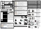
After inserting DVP-F232 card into MPU, you can use WPL to monitor or upload or download via
MODEM connection. First, you should connect PC and PLC to MODEM separately at the two end of
network and turn MODEM power on to operate by following steps.
PC
WPLSoft is executing
DVP-EP/EH series MPU
DVP-F232 interface
MODEM
MODEM
telecommunication
network
STEP 1: Setting M1184=On on PLC side (start-up MODEM)
STEP 2: Setting M1185=On (start-up PLC’s MODEM initialization)
STEP 3: Check the result of MODEM initialization: M1186=On means succeed to initial. M1187=On
means fail to initial.
STEP 4: After initialing successful, WPL software can be ready for connection on remote PC side. WPL
connection method: setting -> modem connection (you need to install modem’s driver first) -> to
get dial connection dialog box and then fill in dial information as following.
If you dial a number to access an outside line, what is it? Please fill in this
field when it is necessary.
Telephone number
: if there is any area code or city code, you don’t need
to put anything for distinction. Only key the figure one by one directly.
For example: 88633626301
Extension number:
Please fill in the field when it is necessary.
Dialing times:
setting redial times when it is fail to connect.
After finishing input, execute dialing to start connection.
After dialing connection successfully, dial connection dialog box will disappear automatically. Now,
you can monitor remote PLC via WPL. If there is remote control signal detected on PLC side, M1188
will be On and user can know if PLC is monitored by remote control via this special M.
Note:
1. Communication baud rate can’t be changed during MODEM connection. MODEM connection
baud rate on PLC side is fixed to 9600bps and can’t be modified.
2. The MODEM that connected to PLC must provide Auto Answer (AA) function. Communication
baud rate for MODEM at two end should be 9600bps and higher.
3. EP/EH series special M definition for MODEM connection: (following special M is valid when PLC is
RUN/STOP.
Device Function Explanation Remark
M1184 Start-up MODEM When M1184=On, following actions are valid.
M1185 Start-up MODEM initialization This flag will be Off after finishing initialization.
M1186 Fail to initial MODEM When M1185=On, M1186=Off.
M1187 Succeed to initial MODEM When M1185=On,M1187=Off.
M1188 Display if MODEM is connected or not On means in connection
4. Additional explanation on PLC side:
a) It must use with RS-232 card when connecting MODEM on PLC side. If not, above special M
are invalid.
b) You must set M1185=On to initial MODEM after MODEM start-up (M1184=On). If not, it can’t
start-up MODEM auto dial function on PLC side.
c) MODEM will enter auto dial mode after initialization.
d) MODEM will enter to ready for dial mode on PLC side after remote PC stops connection. If user
turn MODEM power off now, it should need to initial at the next time when turning on MODEM.
e) The initial format that used to MODEM on PLC side are ATZ and ATS0=1.
DVP-F422
(RS-422
card)
Terminal Layout
Tx+
Tx
-
Rx+
Rx-
GND
Tx+: transmission
(+)
Tx-: transmission
(-)
Rx+: receive (+)
Rx-: receive (-)
User can use COM2 to connect RS-422 and HMI or other
peripheral for long distance connection. The communication
function is the same as COM2 except communication
interface. Note: PLC will set that COM2 is occupied by RS-422
card and built-in COM2 (RS-485) function will be invalid after
inserting this card. Refer to following for system connection.
Wiring example
1
2
3
4
6
7
8
9
DVP-F422 COM2/DB-9
PLC COM2
Delta HMI seriesDOPA
2
1
3
4
MODE 1: RS-232
MODE 2: RS-422
MODE 3: RS-485
Delta HMI series:DOPA RS-422 is at
COM2, and need to set to MODE 2,
Refer to following for setting :
○ ○
DVP-F2AD
Terminal layout
V0+
I0+
V1+
I1+
COM
CH0
CH1
Voltage input
0~10V
0~10V
V0+
I0+
V1+
I1+
COM
CH0
CH1
current input
0~20mA
0~20mA
Input signal limit:
Voltage: less than 12VDC
(Inputting negative voltage
is banned)
Current: less than 30mA
(Inputting negative current
is banned)
There are 2 analog input points supported by F2AD card and
their characteristics are shown in the following:
Item Voltage input Current input
Analog signal DC 0~+10V DC 0~20mA
Resolution
(12bit)
2.5mV (10/4000) 10uA (20/2000)
Input
impedance
40KΩ 250Ω
update time
for conversion
D1118 setting (≧K5, unit: ms)
Characteristic
cure
4000
10V
0
Digital
output
voltage input
0
20mA
2000
Digital
output
current input
Current value D1056 (CH0) D1057 (CH1)
Digital value
output
Average value D1110 (CH0) D1111 (CH1)
User can get A/D conversion value saved in special D by
reading special D that corresponds to current value or average
value. D1118 setting is every update time of current value of
digital value output.
○ ○
Applicable
Model
Model Name Outline Function Explanation
EP EH
DVP-F2DA
Terminal layout
V0+
I0+
V1+
I1+
COM
0~+10V
0~+10V
CH0
CH1
Voltage output
output load: 1K~2MΩ
V0+
I0+
V1+
I1+
COM
CH0
CH1
current output
0~20mA
0~20mA
output load: 0~500Ω
There are 2 analog output points supported by F2DA card and
their characteristics are shown in the following:
Item Voltage output Current output
Analog signal DC 0~+10V DC 4~20mA
Output
impedance
Less than 0.5Ω Less than 0.5Ω
Resolution
(12bit)
2.5mV (10/4000) 5uA (20/4000)
Update time
for conversion
D1118 setting (≧K5, unit: ms)
Digital value
input
D1116 (CH0) D1117 (CH1)
Characteristic
cure
4000
10V
0
voltage
output
digital input
digital input
0
20mA
4000
current
output
User can move value to D1116(CH0) or D1117(CH1) to get
correspondent output voltage by using instruction MOV.
○ ○
DVP-F232S
(RS-232
card)
Terminal Layout (DB-9
female)
GND
Tx
Rx
5
3
2
1
9
8
7
6
4
NC
NC
NC
NC
NC
NC
Note:
Please pay attention to
signal of pin2 and pin3
when this
communication port is
connected to PC or
HMI. Especial that this
definition is different
from DVP-F232 card.
DVP-F485S
(RS-485
card)
D+
D-
D + : signal
(+)
D - : signal
(-)
When two built-in COM1(RS-232) and COM2 (RS-485)
are not enough for use, you can add one COM by this card
(number is 3 and is called COM3. There are two interfaces,
RS-232 and RS-485, for you to use. Its general function is the
same as COM1 but communication baud rate is
9600/19200/38400 bps. PLC scan time will be added at least
0.8ms ~ 2ms due to COM3.
Usage limit: PC1 and PC2 can’t execute ladder diagram
monitor function simultaneously when COM2 is slave mode
and connect to PC1 with executing WPLSoft and COM3 also
connects to PC2 with executing WPLSoft. But other
communication function is normal. COM1 is out of this limit.
MasterPC 2
HMI
PC
PC 1
HMI
COM1
COM2
COM3
(RS-232)
(RS-485)
DVP-F232S or DVP-F485S
DVP EH MPU
AC drive or Servo
Extension card for
communication port
select one Master device
or
╳ ○
This digital DIP switch card provides
8 On/Off input signals (DI0~DI7) to
read value by using instruction API
109 SWRD. It is general used to be
input interface of external data setting
and doesn’t occupy input point X.
ID0
M1104
M1105
M1106
M1107
M1108
M1109
M1110
M1111
ID1
ID2
ID3
ID4
ID5
ID6
ID7
DVP-F8ID
After system finishes every scan time, it will auto to read 8 bits
of digital switch and set each state in special auxiliary relay
M1104~M1111. User can use this 8 special M to operate in the
program. Refer to following example:
M1000
MOV
K2M1104 D1120
Setting PLC ID by DIP switch
○ ○
DVP-F4IP
Terminal layout and
wiring
+24V
S/S
AX0
AX1
AX2
AX3
M1104
M1105
M1106
M1107
F4IP card provides 4 digital input points with photo coupler
isolation between PLC. After system finishes scan every time,
it will read 4 bits of these 4 digital input points automatically
and set the states separately in M1104~M1107. User can
operate this four special M in the program directly.
Item Input Spec.
Input type
DC(SINK or SOURCE)
Input signal current About 5mA/DC24V
Off→On, 16VDC and higher
Action level
On→Off, 14.4VDC and lower
○ ○