


Applicable
Model
Model
Name
Outline Function Explanation
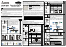
EP EH
There are 2 digital output
points that provided by
F2OT card. Output type is
transistor and user can
driver output points by using
M1112 and M1113.
A
Y0
A
C0
A
Y1
A
C1
.
M1112
M1113
DVP-F2OT
Item Current spec. Voltage spec. Max. load Response time
Output
spec.
0.3A/1point 30VDC 9W/1point
Off→On 20us
On→Off 30us
○ ○
DVP-F6VR
There are two built-in analog knob VR0 and
VR1 in EP/EH MPU. You can expand analog
input equip to VR2~VR7 by using this VR card.
Refer to API85 VRRD and API86 VRSC in
application manual (programming) for detail.
VR2 VR3
VR4
VR5
VR6
VR7
○
○
DVP-256FM
256FM is a data backup memory card. There is a switch on it
and PLC will check the state of this switch when PLC is power
on. If this switch is Off, memory card will be invalid. And it is
invalid to change the switch when PLC is power on. All
memory data read/write action will be valid when switch is On.
╳ ○
It will check password during date copy. If
there is password in memory card, it will also be
copied to PLC and PLC will be locked. See
flowchart at the right side.
There are several sections for copy data in
memory to PLC as shown in the following.
Data block Setting range Default
Program area 15872 Steps All are NOP
instruction
Data register D0~D999 K0
D1035, D1038 K0
D1101 K0
D1102 K1600
D1103 K2000
D1200 K500
D1201 K999
D1202 K2000
D1203 K4095
D1204~D1207 K-1
D1208 K100
D1209 K199
D1210 K220
D1211 K234
D1212 K235
D1213 K255
D1214 K500
D1215 K899
D1216 K200
D1217 K999
D1218 K2000
D1219 K9999
D2000~D9999 K0
File register 0~4999 K0
M0~M999 Off
M1035, M1101 Off
Auxiliary relay
M2000~M4095 Off
Step point S0~S1023 Off
Timer T0~T255 K0
Counter C0~C255 K0
Password 4 words Off
OFF
ON
The flowchart for uploading data to PLC
when installing on MPU and power is on:
check switch
memory card
is invalid
check PLC
password
no password
lock with password
password is
correct or not?
correct
incorrect
check if there is
password in
memory card
no password
lock with
password
copy data in
memory card
to PLC
memory card
won be active
copy password in
memory card to PLC
to be as PLC
password
Therefore, 256FM card can be used for data
backup and PLC copy. It can write PLC major
data block (according to left table) into memory
card according to following two steps. Step 1:
finish setting program parameters, file register
parameters or other relative latched parameters
by using WPLSoft or HPP02. Step 2: choose
communication -> communication for memory
card in WPLSoft software. You can insert this
memory card into other EH MPU to finish PLC
copy function quickly. After this PLC MPU is
power on, the data in memory card will upload to
PLC relative data area. (only for DVP-EH MPU
(32 points and more))
Those data in 256FM card can be read/wrote
by using WPLSoft or HPP02 but there is limit for
editing or read/write data. For HPP02, it can only
read/write the DATA in program area and file
register area.
When inserting memory card in PLC, you can read/write data in memory card by using WPL. The
operations are in the following: (please confirm that switch on memory card is On before PLC is power
on. And also confirm that connection is successful to read/write data in memory card.
Using WPLSoft to select communication ->
communication for memory card
There are three modes:
PLC memorymemory card
You can copy data in memory card to PLC or copy
data in PLC to memory card.
WPL working areamemory card [program]
It can copy program that edited by WPL to memory
card or copy PLC program in memory card to WPL
working area.
WPL working area memory card [commentary]
It can copy commentary in WPL to memory card or
read commentary from memory card (commentary
in memory card can be only loaded in WPL working
area. It can’t be loaded in PLC EH MPU and there
is no area for saving commentary in EH MPU.)
Following is the operation for each item and relative cautions:
Data transmission between PLC memory card
Function selection
PLC => memory card
a) If password in PLC is unlocked but password in memory card is locked,
data will be wrote into memory card and password in memory card will be
disable after executing PLC => memory card.
b) If password in PLC is locked and no matter password in memory card is
locked or not, data and password in PLC will be wrote into memory card
after executing PLC => memory card.
memory card => PLC (PLC must be in STOP mode)
It will compare password in memory to password in PLC before executing. If
passwords are not the same, it can’t read data.
Note: “Lock state” means password in memory card is locked.
Data is transmitted between WPL working area memory card [program]
Function selection
WPL working area => memory card
a) If you don’t input any words in password field (password field is blank),
password in memory card will be clear after pressing Enter button (no
matter it has password or not before).
b) If you input new password in password field, password in memory card
will be protected by this new password.
memory card => WPL working area
If there is password for memory card, you will be asked to input password
when executing this function. If you don’t input password or input error
password, it will have error message and can’t read data.
Note: “Lock state” means password in memory card is locked.
Data transmitted between WPL working area memory card [commentary]
Function selection
WPL working area => memory card
a) You can select devices to save in memory card. Default is all devices.
After you select, all device you select with commentary will save in
memory card.
b) For device M and D, special D(D1000~D1999) and special
M(M1000~M1999) won’t be wrote into memory card.
c) The commentary capacity in memory card is 32KB. It can save 16000
Chinese words or 32000 letters.
Memory card => WPL working area
To upload commentary in memory card to WPL working area for user to edit
or modify.
Note: “Lock state” means password in memory card is locked.
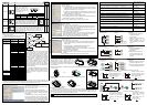
3 Installation and Maintenance
Please make sure that PLC is power off and
open extension slot cover before installing or
removing function card or memory card. The
installed position of function card and memory card
are shown at the right side. Please attach terminal
label shipped with package on correct terminal to
avoid error wiring.
B
Function card installation – Please put function card into slot vertically and tighten accessory screws into
correct position.
B
Remove function card
Backup memory card installation (change switch to On or Off by requirement)
and removal
Installation
Removal
Check for finishing installation
After PLC is power on, connect PLC to WPLSoft at PC side. In WPLSoft, select view -> working
area and then select connected model to connect. At this time, WPLSoft will detect configuration of PLC
MPU system and show the result, including categories of function card and state of memory card (On or
Off), in working area. Refer to WPLSoft user manual for detail.
4 Application
All kinds of function card provided by DVP series solve the problem that happened in PLC application.
For example:
Usage timing and application requirement
solution (correspond to
function card model name)
When system specification is modified, there are not enough points for
use. And you need only 1~4 input points or 1~2 output points.
Use DVP-F4IP or
DVP-F2OT
Output point of MPU is relay and you need 1~2 points more with transistor
type.
Use DVP-2OT
There is space limit for installing and need to deal with analog signal. Use DVP-F2AD or
DVP-F2DA
You need 1~2 analog output points to control AC drive speed. Use DVP-F2DA
Small control system and need 1~2 analog input points. Use DVP-F2AD
You need to connect PLC to PC and HMI and also control AC drive. Use DVP-F232S or
DVP-F485S
There are many PLCs and need to download program quickly. (copy PLC) Use DVP-256FM
When parameters want to set by DIP switch without occupy any input
points.
Use DVP-F8ID
When built-in COM 2 is RS-485, but what you need is RS-232 or RS-422. Use DVP-F232 or
DVP-F422
When remote control PLC is by MODEM. Use DVP-F232
When there are 3~8 variables needed to modify by requirement very
often.
Use DVP-F6VR
Following is application for DI/DO card and AI/AO card:
DVP-F4IP application:
Terminal Layout
DC24V
S/S
AX0
AX1
AX2
AX3
switch 1
switch 2
switch 3
detector
Program
M1104
M1107
M1106
M10
M11
Y0
TMR T0
K1000
M1105
Explanation
1 The input terminals AX0~AX3
correspond to devices
M1104~M1109
2 Adding input points AX0~AX3.
External switches 1~3 and
detector control M10, M11, Y0
and T0 separately according to
program.
DVP-F2OT application:
Terminal Layout
AY0
AC0
AY1
AC1
DC5~30V
F1
F2
external load 1
external load 2
F1 and F2 are fuses with 0.5A
Program
X10
M10
M1112
M1113
Explanation
1 The output terminals AY0~AY1
correspond to devices
M1112~M1113.
2 Adding output points AY0 and
AY1 and connect to load 1 and
load 2 to be controlled by X10
and M10.
DVP-F2AD application:
Terminal Layout
V0+
I0+
V1+
I1+
COM
detector (voltage)
detector (current)
GND
common terminal
Program
M1000
MOV D1056 D0
MOV D1110 D1
CH0
M1000
MOV
MOV
CH1
D11
D1057
D1111
D10
Explanation
1 CH0 AD is variable. Current value
is D0 and average value is D1.
2 CH1 AD is variable. Current value
is D10 and average value is D11.
Conversion calculation of CH0 AD: Conversion calculation of CH1 AD:
4000
1472
0
+10V
?
Digital
output
analog input
Detector (voltage) produces
an input voltage CH0. If the
value D1 reads is K1472, it
means input voltage is
V
V
68.3
4000
10
1472 =×=
0
?
2000
1234
20mA
digital
output
analog input
Detector (current) produces
an input current CH1. If the
value D11 reads is K1234, it
means input current is
mA
mA
34.12
2000
20
1234 =×=
DVP-F2DA application:
Terminal layout
V0+
I0+
V1+
I1+
COM
ACM
AVI
ACM
ACI
current output
AC drive 1
voltage output
AC drive 2
Program
MOV D0
D1116
CH0
MOV CH1
D1117D1
M1000
M1000
Conversion calculation of CH0 DA: Conversion calculation of CH1 DA:
0
?
12.34
20mA
4000
analog
output
digital output
The current is outputted to
ACI of AC drive to be speed
control. If you need current
12.34mA, you should give
D0:
2468
20
4000
34.12 =×=
mA
mA
0
?
4000
5.23
+10V
analog
output
digital input
The voltage is outputted
to AVI of AC drive to be
speed control. If you
need voltage 5.23V, you
should give D1:
2092
10
4000
23.5 =×=
V
V