


http://www.delta.com.tw/industrialautomation/
5011655400-ENE0
2007-06-22
Ethernet Communication Module
Instruction Sheet
Warning
This instruction sheet only provides introductory information on electrical specification, general specifications,
installation, basic operation and settings of DVPEN01-SL.. For more detailed information on the network protocols,
please refer to relevant references or literatures.
This is an OPEN TYPE PLC. The PLC should be kept in an enclosure away from airborne dust, humidity, electric shock
risk and vibration. Also, it is equipped with protective methods such as some special tools or keys for opening the
enclosure, in order to prevent hazard to users or damage on the PLC.
Please read this instruction sheet carefully before use and follow this instruction to operate the device in order to prevent
damages on the product or injuries to staff.
Introduction
Functions:
Supports MODBUS TCP/IP
Supports Master and Salve Data Exchange
DVP28SV Automatic Time Correction
Supports E-Mail
RS-232/Ethernet Configuration
Transmission Speed: 10/100 Mbps
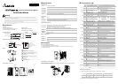
Nameplate Explanation IP Label MAC Address
24Vdc 1.5W
MADE IN XXXXXX
EN01-SL 0T7040001
VX.XXXX
IP ADDRESS
SUBNET MASK
001823100022
PLC Model Name
Bar-code, Serial No.
Power Input Spec.
Version
Model Name and Serial Number Explanations:
EN: Ethernet
EN
DVP series
Model type
Communication module
Left-side module
For SV series MPU
Left-side module
Production No.
Production week
Production year (2006)
Production plant (Taoyuan
)
Version No.
M
ode
l n
a
m
e
Type 01
Outline:
LAN
RS-232
LINK
DVPEN01
RS-232
POWER
100M
1
4
3
7
5
6
9
8
2
1
Model name
2
Extension Port to connect Device
3
Extension Port to connect Extension module
4
POWER, LINK, RS-232, 100M LED
5
DIN rail clip
6
Extension hole for mounting unit or module
7
Extension clip
8
RS-232 port
9
Ethernet RJ-45 port
Product Profile: Unit mm [inchs]
LAN
RS-232
LINK
DVPEN01
RS-232
POWER
100M
60 [2.362]
90 [3.543]
3 [0.118]
Specifications
Network Interface
Interface RJ-45 with Auto MDI/MDIX
Number of
ports
1 Port
Transmission
method
IEEE 802.3, IEEE 802.3u
Transmission
cable
Category 5e (TIA/EIA-568-A,TIA/EIA-568-B)
Transmission
Rate
10/100 Mbps Auto-Detect
Protocol ICMP, IP, TCP, UDP, DHCP, SMTP, NTP, MODBUS TCP
Serial Interface
Interface RS-232
Number of
Ports
1 Port
Transmission
Cable
DVPACAB230, DVPACAB215, DVPACAB2A30, DVPACAB2B10
Environmental Specifications
Noise Immunity
ESD (IEC 61131-2, IEC 61000-4-2): 8KV Air Discharge
EFT (IEC 61131-2, IEC 61000-4-4): Power Line: 2KV, Communication I/O: 1KV
Damped-Oscillatory Wave: Power Line: 1KV, Digital I/O: 1KV
RS (IEC 61131-2, IEC 61000-4-3): 26MHz ~ 1GHz, 10V/m
Environment
Operation: 0°C ~ 55°C (Temperature), 50 ~ 95% (Humidity), Pollution degree 2;
Storage: -40°C ~ 70°C (Temperature), 5 ~ 95% (Humidity)
Vibration/
Shock
Resistance
Standard: IEC61131-2, IEC 68-2-6 (TEST Fc)/IEC61131-2 & IEC 68-2-27 (TEST Ea)
Approvals
IEC 61131-2, UL508
Electrical Specifications
Power supply
voltage
24VDC (-15% ~ 20%) (Power is supplied by the internal bus of MPU.)
Power
Consumption
1.5W
Insulation
voltage
500V
Weight (g) 92 (g)
Installation
How to Connect DVPEN01-SL with PLC
1. Adjust the extension clip on the left side of the MPU.
2. Meet the extension port of the MPU with DVPEN01-SL and connect them as the figure shown below.
3. Fasten the extension clip.
DVP28SV
LAN
RS-232
RS-232
LINK
100M
DVPEN01
POWER
Install DVPEN01-SL with Other Module
To connect DVPEN01-SL with the other extension module, lift the extension clip of the extension module by a
screwdriver and open the side cover.
Control Register (CR)
CR NO.
HW LW
Type Register Description
#0 R
Model NO
Read only; DVPEN01-SL model NO.=H’4050
#1 R Firmware version
System firmware version; The type is hex. For
example, H’0100 means the firmware version is v1.00.
b0 Modbus TCP mode setting
#2 R Communication Mode
b1 Data Exchange mode setting
#3 W E-Mail Event 1 Trigger Set as 1 to send the E-mail 1.
#4 W E-Mail Event 2 Trigger Set as 1 to send the E-mail 2.
#5 W E-Mail Event 3 Trigger Set as 1 to send the E-mail 3.
#6 W E-Mail Event 4 Trigger Set as 1 to send the E-mail 4.
#7 R E-Mail 1, 2 Status Register b0~b7 Status of E-Mail 2
b8~b1
5
Status of E-Mail 1
#8 R E-Mail 3, 4 Status Register b0~b7 Status of E-Mail 4
b8~b1
5
Status of E-Mail 3
#9 R/W E-Mail 1 Additional Message User fills the message, and it will be send by E-Mail.
#10 R/W E-Mail 2 Additional Message User fills the message, and it will be send by E-Mail.
#11 R/W E-Mail 3 Additional Message User fills the message, and it will be send by E-Mail.
#12 R/W E-Mail 4 Additional Message User fills the message, and it will be send by E-Mail.
#13 R/W Data Exchange trigger Set as 1 to start the Data Exchange transaction.
#14 R Data Exchange Status Register Status of Data Exchange transaction
#24 ~ #15 Reserved Reserved
#26 #25 R/W Destination IP Destination IP address for Data Exchange
#27 Reserved Reserved
#28 R/W Destination Slave ID Destination Slave ID for Data Exchange
#48 ~ #29 R/W Default Transmission Buffer Transmitted data buffer for Data Exchange mode
#68 ~ #49 R Default Received Buffer Received data buffer for Data Exchange mode
#69 R/W DHCP/Static IP Select DHCP Mode or Static IP
#71 #70 R/W IP Address IP Address
#73 #72 R/W Subnet Mask Subnet Mask of DVPEN01-SL
#75 #74 R/W Gateway Default gateway IP address
#76 R Network Status Register Status of IP address setting
#80 ~ #77 Reserved Reserved
#81
R/W Slave Transmission Buffer Address Slave Transmission buffer Address for Data Exchange
#82
R/W Number of Received Registers Number of Received Registers
#83
R/W Master Received Buffer Address Master Received Buffer Address for Data Exchange
#84
R/W Slave Received Buffer Address Slave Received Buffer Address for Data Exchange
#85
R/W Number of Sending Registers Number of Sending Registers
#86
R/W Master Transmission Buffer Address
Master Transmission Buffer Address for Data
Exchange
#110 ~ #87 Reserved Reserved
#111
R/W Modbus TCP Operating Mode Set as 1 to configure Modbus TCP be the 8 bits mode.
#113 ~ #112
Reserved Reserved
#114 R/W Modbus TCP Time-Out
Modbus TCP transaction time-out (ms)
#115 R/W Modbus TCP Trigger Set as 1 to send Modbus command.
#116 R/W Modbus TCP Status Register Status of Modbus TCP transaction
#118 ~#117 R/W Modbus TCP Destination IP
The Destination IP Address of Modbus TCP
transaction
#119 R/W Modbus TCP Data Length Data length of Modbus TCP in CR#120 ~ CR#219
#219~#120 R/W Modbus TCP Data Buffer
Data buffer of Modbus TCP Mode for storing
sending/receiving data
#250~#220 Reserved Reserved
#251 R Error Code The EVPEN01-SL error code
#255~#252 Reserved Reserved
Symbol definition
R: Read
W: Write
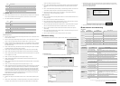
Basic Configuration and Status
CR#2: Communication mode setting: Set as 0 to Disable; Set as 1 to Enable.
bit # Mode bit # = 0 bit # = 1
b0 Modbus TCP Mode Modbus TCP Mode Disable Modbus TCP Mode Enable
b1
Data Exchange
Mode
Data Exchange Mode Disable Data Exchange Mode Enable
CR#251: Error codes; See the table in the next page.