


CR#251 Error status
b0 Not connected.
b1 IP setting error.
b2 CR#13 is set as data sending but data exchange is disabled.
b3 CR#13 is set as data sending but the data exchange mode has not been enabled.
b4 Connecting to NTP Server fails.
b7 Connecting to SMTP Server fails.
b8 DHCP does not acquire correct network parameters.
Sending E-mail Function
CR#3 ~ CR#6:E-mail will be sent when set as 1. After the E-Mail sending is completed, the CR value will be
set as 0. Please use differential command to trigger CR#3 ~ CR#6 in order to avoid continual mails.
CR#7, CR#8: E-Mail Status. See the table below.
CR Value E-Mail Status
0 Nothing
1 Processing
2 Success
3 ~ 9 Reserve
10 Cannot connect to SMTP-Server
11 E-mail Address error
12 Error response SMTP-Server transmission error
13 No free TCP connection
14 ~ 255 Reserve
CR#9 ~ CR#12: The register value will be stored in E-Mail Subject to be the user message.
Data Exchange Function
CR#13: The data in Data Exchange Buffer will be exchanged when CR#13 is set as 1. CR#13 will be set as 0
when the transaction is finished.
CR#14: The status register of Data Exchange transaction. CR#14 = 1 refers to the transaction is in progress.
CR#14 = 2 refers to the Data Exchange transaction is completed. CR#14 = 3 when an error occurs.
CR#28: The Destination Salve ID for Data Exchange. Range: K1 ~ K255. DVPEN01-SL will look up the Slave
IP address in the Slave ID–IP lists of Data Exchange function. When CR#28 is set as 0, CR#25 and CR#26
will be the Slave IP Address.
CR#25 ~ CR#26: Before setting up the destination IP address of Data Exchange Mode, please set CR#28 as
0. See CR#70 and CR#71 for the steps of setting up IP address.
CR#29 ~ CR#48: The default Data Exchange registers for storing the data to be sent to the remote MPU.
CR#49 ~ CR#68: The default Data Exchange registers for storing the received data from the remote MPU.
CR#81:Setting the Modbus Address of Sending Buffer in Slave for Data Exchange Mode. It’s only permitted
to use D Registers. Ex. D0 = H1000.
CR#82:The number of reading registers for data exchange Mode. Range: K1 ~ K128.
CR#83:Setting the Modbus Address of Receiving Buffer in Master for Data Exchange Mode. It’s only
permitted to use D Registers.
CR#84:Setting the Modbus Address of Receiving Buffer in Slave Data Exchange Mode. It’s only permitted to
use D Registers.
CR#85:The number of sending registers for data exchange Mode. Range: K1 ~ K128.
CR#86:Setting the Modbus Address of Sending Buffer in Master for Data Exchange Mode. It’s only permitted
to use D Registers. For example, set CR#81 as H1000 (D0), set CR#82 as K1, and set CR#83 as H1064
(D100). When the Data Exchange is executed, It will read the Slave’s D0 and write into the D100 in Master.
Set CR#84 as H1002 (D2), set CR#85 as K4, and set CR#86 as H1008 (D8). When the Data Exchange is
executed, It will read Master’s D8~D11 and write into Slave’s D2~D5. The sending and receiving functions can
be executed at one time. If both values of CR#82 and CR#85 are 0, default sending and receiving buffers
(CR#29~CR#68) and default register number (K20) will be used.
Network Configuration Function
CR#69: IP mode setting. Set as 0 to be Static IP address; Set as 1 to obtain IP address by DHCP (Dynamic
IP).
CR#70 ~ CR#71: IP Address setting. It’s accessed through Hex Mode. It cannot write when in DHCP Mode.
For example, if the user wants to set the IP as 192.168.0.2, write H’0002 to CR#70 and H’C0A8 to CR#71.
(K192 = H’C0, K168 = H’A8, K0 = H’00, K2 = H’02)
CR#72 ~ CR#73: Subnet Mask setting. It’s accessed through Hex Mode. It cannot write when in DHCP Mode.
For example, if the user wants set Subnet Mask as 255.255.255.0, write H’FF00 to CR#72 and H’FFFF to
CR#73.
CR#74 ~ CR#75: Default Gateway IP Address setting. It’s accessed through Hex Mode. It cannot write when
in DHCP Mode. See CR#70 and CR#71 for the steps of Default Gateway IP Address setting.
CR#76: Status of IP Address. CR#76 = 0 refers to normal; CR#76 = 1 refers to DHCP transaction is in
progress; CR#76 = 2 refers to IP Address setting is in progress.
Modbus TCP Function
CR#111:The Modbus TCP communicating Mode. Set CR#111 as 1 to be the 8 bits Mode. Set CR#111 as 0 to
be the 16 bits Mode.
CR#114: CR#114 is the time-out of Modbus TCP transaction (ms).
CR#115: The Modbus TCP transaction will start when CR#115 is set as 1. CR#115 will be set as 0 when the
transaction is finished. Please use differential instruction to trigger CR#115.
CR#116: The status register of Modbus TCP transaction. CR#116 = 1 refers to the transaction is in progress.
CR#116 = 2 refers to the Modbus TCP transaction is completed. CR#116 = 3 when an error occurs.
CR#117 ~ CR#118: Destination IP address of Modbus TCP. See CR#70 and CR#71 for the steps of IP
address setting.
CR#119: The data length of Modbus TCP in CR#120 ~ CR#247. In the 8 bits mode, the range is K1 to K100.
In the 16 bits mode, the range is K1 to K200.
CR#120 ~ CR#247: Modbus TCP registers for storing the data to be sent and received.
Software Setting
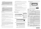
Communication: Start WPLSoft and click on “Options” and select “Ethernet” in “Communication Setting”.
DVPEN01-SL Settings
1. Click on the “auto search” and WPLSoft will search for all DVPEN01-SL in the network.
2. WPL displays all DVPEN01-SL in the network. Click on the desired module and click twice again to open the
setup screen.
3. Enter the “Network” setup screen to modify the network setting. If there exists DHCP Server in the network,
the user may use DHCP to automatically acquire the network configuration parameters or use Static IP to set
up the network configuration parameters.
4. Click “OK” after completing the settings.
5. After returning to the screen 2, click on the desired module to start communicating.
LED Indication & Troubleshooting
LED Indication
LED LED Status Indication How to deal with
Green constantly on Power supply is normal None
POWER
Green constantly off No power supply Check if the module is powered.
Red flashes
Data are being transmitted
in the serial port
None
RS-232
Red constantly off No data transmission
Check if the RS-232 cable is connected when
using RS-232 communication.
Orange constantly on Transmission speed: 100M None
100M
Orange constantly off Transmission speed: 10M
Check if the network transmission speed is
100M.
Green constantly on Network works normally None
Green flashes Network is working None
LINK
Green constantly off Network is not connected Check if the RJ-45 cable is tightly connected.
Troubleshooting
Abnormality Cause How to deal with
MPU is not powered
Check if the MPU is powered and whether the power supply
is normal.
POWER LED off
Not connected to MPU Check if DVPEN01-SL is tightly connected with MPU.
Not connected to the network
Check if the RJ-45 cable is correctly connected to the
network.
LINK LED off
RJ-45 poor contact
Check if the RJ45 contact is tightly connected to the Ethernet
RJ-45 port.
The module is not connected
to the network
Check if the RJ-45 cable is correctly connected to the
network.
Transmission speed: 10M Check if the network transmission speed is 100M.
100M LED off
RJ-45 poor contact
Check if the RJ45 contact is tightly connected to the Ethernet
RJ-45 port.
Not connected to the network Check if DVPEN01-SL is correctly connected to the network.
Unable to locate a
module
The computer and MPU are
blocked by the firewall.
Search by IP address or use RS-232 for settings.
Not connected to the network Check if DVPEN01-SL is correctly connected to the network.
Incorrect communication
settings in WPLSoft
Check if you select “Ethernet” in the communication settings.
Unable to open
DVPEN01-SL
setup screen
The computer and MPU are
blocked by the firewall.
Use RS-232 for settings.
Fail to up/down
load program and
monitor by
WPLSoft
The network setting of
DVPEN01-SL is incorrect
Check if the network setting of DVPEN01-SL is correct.
Consult the IT staff if you are using the Intranet in the
company or refer to the network setting instructions provided
by your ISP.
DVPEN01-SL settings are
incorrect
Check if the settings of DVPEN01-SL are correct.
Incorrect CR settings Check if the CR is used correctly.
Unable to send out
emails
Incorrect settings of mail
server
Check the IP address of SMTP-Server.
The content of this instruction sheet may be revised without prior notice. Please consult our distributors o
r
download the most updated version at http://www.delta.com.tw/industrialautomation