


http://www.delta.com.tw/industrialautomation/
5011637600-FME0
2005-07-08
DVP Peripheral Series
Frequency Measurement Card
Instruction Sheet
1 WARNING
This frequency measurement card is a specific function card for DVP-EH PLC, please use this card with
DVP-EH MPU.
Frequency measurement card is an OPEN TYPE without any mechnical shield. When installing this card,
user is supposed to power off the MPU and take precaution against static (anti-static glove) to prevent the
surface parts of the card from being damaged.
Do NOT connect the AC power line to any of the input/output terminals, or it will damage the PLC. Make sure
all the wiring is correct before power on.
To enhance the anti-interference performance of product, please make sure terminal FG is properly
grounded.
Frequency measurement card is only workable for the DVP-EH with the version greater than 1.1.
2 INTRODUCTION
Thank you for choosing Delta DVP series product. The frequency measurement card (DVP-F2FR) is the
function card with 2 external inputs that accept digital signals. By using FROM-TO instruction, PLC can
read/write the data or parameter in the frequency measurement card.
There are 255 built-in CRs (Control Register) in DVP-F2FR with 16 bits for each register. DVP-EH MPU can
control the function of DVP-F2FR by programming the CRs.
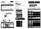
Nameplate Explanation:
Model:
VX.XX
MADE IN XXXXXX
DVPF2FR0T5280001
DVP-F2FR
Mode Number
Serial Number & Barcode
Version
Serial Number Explanation:
Production number
Production week
Production year 2005
Production factory (Taoyuan plant)
Version type
Production model
Product Outline:
Power indicator
Dismounting Holder
(for dismounting from PLC)
Vertical view
Screw hole
Terminal
F0
F1
RUN/STOP indicator
Terminal
3 SPECIFICATION
3.1 Basic Specification:
Electric Level
Terminals [A+] & [A-], [B+] & [B-]: DC22~30V, 8~12mA.
SINK or SOURCE
Input Signal
Pulse Type
t
t
t
t
t
t
1
2
3
1
2
3
t1: rising/falling time ≦0.8us
t2: ON/OFF pulse bandwidth ≧2.5us
t3: phase difference of A, B phase ≧1us
Storage -25
o
C~70
o
C (Temperature), 5~95% (Humidity)
Storage and
Environment
Operation Operation: 0
o
C~55
o
C (Temperature), 50~95% (Humidity), Pollution degree: 2
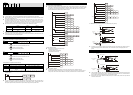
3.2 Operation mode:
There are 3 types of operation mode for the frequency measurement card. User can decide the operation mode by
setting CR1. Detail information as follows:
Mode 1: Pulse Interval Length Measurement (CR1=K1)
Measurement method of pulse interval:
Interval of rising-edge
Interval of falling-edge
Inputs of pulse interval measurement: F0, F1.
Time unit of pulse interval measurement: 50ns, 100ns.
Interrupt function: I180 will be executed after frequency measurement card detects rising edge or falling
edge in F0 and F1. And bit 0 of CR9 will inform interrupt trigger by F0 while bit1 of CR9 by F1. For more
information, please see section 6.1.
Input frequency range: 1Hz~1kHz.
Accuracy: ±0.01% (max.)
Mode 2: High-speed Counter (CR1=K2)
There are 3 types for mode 2 the high-speed counter. The maximum input frequency of Pulse/Direction can be
up to 200kHz. Explanation as follows:
Pulse/Direction: F0 is pulse input point. F1 is the signal to control the count-up or count-down. Counting
method is shown as diagram as follow:
Count down
F0
F1
Count up
Count value
A/B-phase two times frequency: F0 is the input pulse of A phase and F1 is the input pulse of B phase.
Counting method is shown as follow:
Count down
F0
F1
Count up
Count value
F0 (A phase)
Value
Rising-edge Falling-edge
High Count-down Count-up
F1
(B phase)
Low Count-up Count-down
A/B-phase four times frequency: F0 is the input pulse of A phase and F1 is the input pulse of B phase.
Counting method is shown as follow:
F0
F1
Count up
Count down
Count value
Mode 3: Pulse Number Capture (CR1=K3)
Input point: F0 is pulse input point. F1 is the signal to capture pulse number.
Following diagram show the count method of pulse number:
F0
F1
Pulse Captured Period
The calculation of the pulse numbers for F0 is based on the interval between two rising edge or falling
edge of F1.
Interrupt function: when PLC set M1019 (flag of operation mode setting for frequency measurement card)
and D1034 (flag of operation mode setting for frequency measurement card) to set up operation mode,
I180 will be triggered based on the rising-edge or falling-edge of F1. If PLC has I180, it will execute I180.
Accuracy: ±1 pulse.
4 CONTROL REGISTER
DVP-EH MPU perform read/write operation to the CR via programming FROM-TO instruction.
CR will re
Control Register Explanation Table:
CR NO.
HW LW
Attribute
Factory
setting
Latched
Mode Function explanation
#0 R H2A0
°
System default, read only, number=H’2A0
Frequency measurement card execution mode
K1 (mode 1) K2 (mode 2) K3 (mode 3)
#1 R/W* K0
°
Pulse interval
measurement
High-speed counter
Pulse number
capture
Frequency measurement card Run of Stop
K0 K1
#2 R/W K0
°
1,2,3
Stop Run
#3 R/W* K0
°
1,3 F0 record item (range 0~40)
#4 R/W* K0
°
1,3 F1 record item (range 0~40)
Trigger by rising edge or falling edge
rising edge=0, falling-edge=1
CR5 Low byte CR5 High byte
#5 R/W* K0
°
1,3
F0 F1
#6 Reserved
#7 R/W* K2
°
1 F0 measure time unit
#8 R/W* K2
°
1 F1 measure time unit
50ns measure unit K1
100ns measure unit K2
#9 R K0
°
1
Mode 1: interrupt trigger flag
When F0 trigger I180, bit0 of CR9 will be ON.
When F1 trigger I180, bit1 of CR9 will be ON.
When PLC read CR10~CR11, bit0 of CR9 will be OFF.
When PLC read CR12~CR13, bit1 of CR9 will be OFF.
#11 #10 R K0
°
1 F0 pulse interval measurement
#13 #12 R K0
°
1 F1 pulse interval measurement
#15 #14 R K0
°
1 F0 value of frequency floating point
#17 #16 R K0
°
1 F1 value of frequency floating point
#19 #18 R K0
°
1 F0, F1 rising-edge or falling-edge, time difference
#21 #20 R/W K0
°
2 High-speed counter value
High-speed counter value won’t
be cleared when frequency
measurement card stop
High-speed counter mode
K0 K1 K2
#22 R/W* K0
°
2
Pulse/Direction
A/B phase two
times frequency
count
A/B four times
frequency count
Indication flag of count up or count down
K0 K1
#23 R K0
°
2
Count up Count down
Flag of start-up counting of high-speed counter
K0 K1
#24 R/W K0
°
2
Stop counting Start counting
#26 #25 R/W K0
°
3 Number of captured pulse
Method of pulse count
K0 K1
#27 R/W* K0
°
3
Pulse number non-accumulated Pulse number accumulated
#28 R/W K0
°
1 F0 time-out setting (K0~K32767)
#29 R/W K0
°
1 F1 time-out setting (K0~K32767)
#30~#32 Reserved
#33 W* K0
°
Return to factory setting
When writing “1” into CR33, all the CR of frequency measurement
card will return to factory setting and modify former “1” as “0”.
#34 R K0
°
Version explanation: high byte is the value in the left side of decimal
and low b
y
te is the value in the ri
g
ht side of decimal. e.
g
. H1000 is
F0 F1 Value
Rising-edge Falling-edge
Value
Rising-edge Falling-edge
High Count-down Count-up High Count-up Count-downF1
Low Count-up Count-down
F0
Low Count-down Count-up