


CR NO.
HW LW
Attribute
Factory
setting
Latched
Mode Function explanation
V1.00 version.
#35~#49 Reserved
#50 R K51
°
1,3 The index of F0 record value (record the number from CR51~130)
#51~#130 R K0
°
1,3 F0 record value (each value occupy 2 group CR)
#131 R K132
°
1,3 The index of F1 record value (record the number from CR132~211)
#132~#211 R K0
°
1,3 F1 record value (each value occupy 2 group CR)
#222~#255 Reserved
The usage of CR varies based on operation mode. Please follow the table above to read or write CR.
In column Attribute, ‘*” means writing is allowed when frequency measurement card is not working.
When the writing value is out of available range, the value of upper/lower bound shall prevail to write once the
value is out of upper/lower bound.
The CR28 and CR29 are the time-out setting for F0 and F1. When setting them to a non-zero value in mode 1,
it will monitor the signal input from F0 or F1 and start a time-out counting. If no signal detected in F0 and F1 with
the time-out counter reaching the setting, it will clear the CR10~CR11 or CR12~CR13 and inform the PLC by
I180 interrupt. Moreover, when CR28 and CR29 are set to zero, the time-out counter will not work anymore.
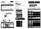
CR50~CR211 will record the value according to the operation mode. Explanation as follows:
Mode 1 Mode 2 Mode 3
CR51~CR130
To record F0 pulse interval (CR10,
CR11)
N/A N/A
CR132~CR211
To record F1 pulse interval (CR12,
CR13)
N/A
To record F1 pulse interval
(CR25, CR26
The index number of each record is plus 2 for CR50 and CR131 after both registers record on next. Once the
index number reaches to the maximum, it will back to the 1
st
index number.
It takes about 125us for instruction FROM/TO to read or write a CR of the frequency measurement card. One
more read/write item of CR, 30us more for register.
5 INSTRUCTION EXPLANATION
5.1 Instruction Explanation for Frequency Measurement Card
API
78 D
FROM
P
Read Special Module CR Data
Instruction
Explanation
: Number of special module (m1=0~7). Number of frequency measurement card, m1=200.
: Number of CR of special module that will be read.
: Location to save reading data.
: Data number of reading one time.
API
79 D
TO
P
Special Module CR Data Write In
Instruction
Explanation
: Number of special module (m1=0~7). Number of frequency measurement card, m1=200.
: Number of CR of special module that will be read.
: Location to save writing data.
: Data number of reading one time
5.2 Explanation of special D, M and Interrupt:
Device Explanation Range
D1034 Mode setting of frequency measurement card D1034 = K1~K3 (Mode 1~Mode 3)
M1019 Flag of mode setting
I180
Frequency measurement card trigger
interrupt
After PLC run at the first scan time, PLC will detect flag M1019 is ON or OFF. If M1019 is ON, PLC will modify
the frequency measurement card’s operation mode based on D1034 setting. Program example as follow is
operation mode 1:
M1002
MOV
K1 D1034
SET M1019
PLC can use M1019 (flag of operation mode setting for frequency measurement card) and D1034 (flag of
operation mode setting for frequency measurement card) to set operation mode 1 (measurement of pulse
interval) and operation mode 2 (measurement of pulse number) to support Interrupt function I180.
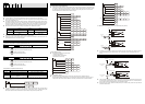
6 APPLICATION EXAMPLE
6.1 Pulse Interval Length Measurement
Following the program example of setting operation mode 1 (D1034, M1019) for frequency measurement card.
For F0 and F1, set the time unit of sampling rate is 100ns (D7, D8) and the sampling record number as 20 (D3,
D4). Moreover, I180 will be triggered when F0 or F1 detects a rising or falling edge. PLC can read CR9 via
instruction FROM to decide which channel to detect the signal.
END
IRET
DMOV D12 D300
D10
FROM K200 K9 K11
DMOV
D9
D300
M1000
M1002
D1034
K200
FROM
K200
FROM K200
M1013
I 180
EI
MOV K1
SET M1019
MOV
MOV
MOV
MOV
TO
K20
K20
K2
K2
D3
D4
D7
D8
K3 D3 K6
K50 D50
K41
K131 D131 K41
FEND
& D9 K1
& D9 K2
6.2 High-speed Counter
The setting for the following program example:
1. Operation mode: Mode 1.
2. Counting method: Pulse/Direction.
3. Set M0=ON to start counting.
END
M1002
D1034
K200
FROM K200
M1013
MOV
SET M1019
MOV
TO
K2
K200
M0
TO K24 K1 K1
K20 D20 K3
K1K22 D22
K0 D22
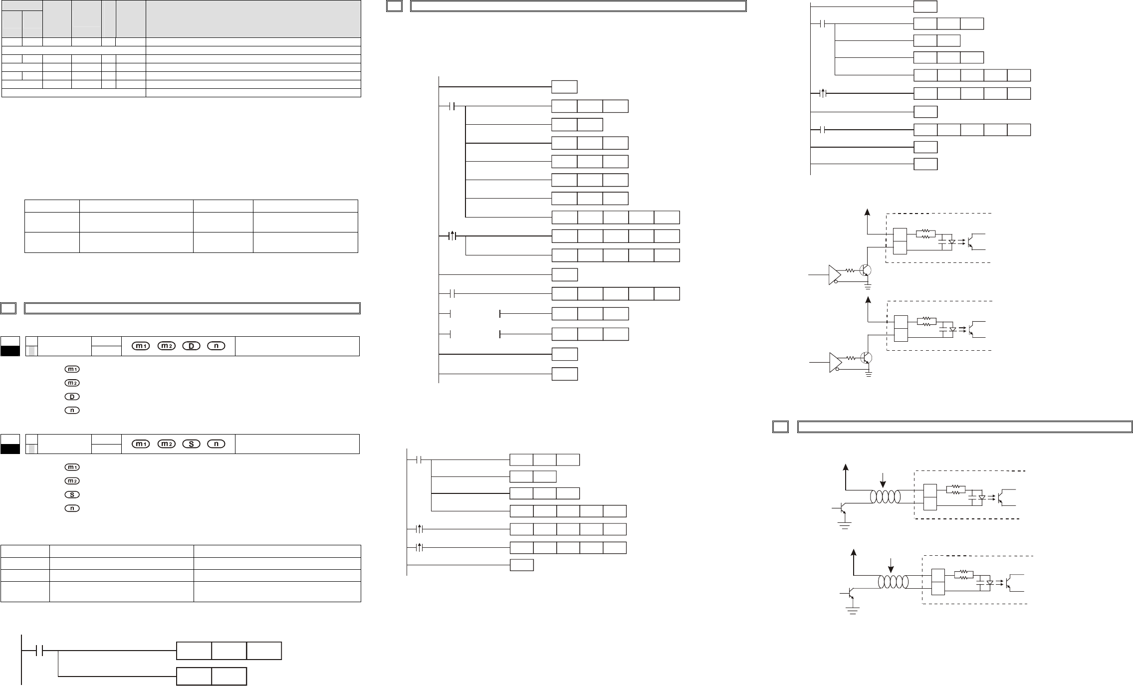
6.3 Pulse Number Capture
The following program example is Mode 3 for frequency measurement card. Whenever frequency
measurement card detects the rising-edge in F1, it will trigger the Interrupt I180 of PLC. When PLC execute
Interrupt I180, it will read the content of CR25, 26 of frequency measurement card via instruction FROM.
M1002
D1034
K200
FROM K200
M1013
MOV
SET M1019
MOV
TO
K200
K20
K1
K3
D4
D4K4
K131
D131
K40
FEND
FROM
END
IRET
K25 D25
K2
M1000
I 180
EI
6.4 Differential Input Interface (please refer to the following wiring method)
A+
A-
+24VDC
4.7K
F0
4.7K
470
Differential
output
NPN Tansistor
ON MMBT4401LT1G
B+
B-
+24VDC
4.7K
F1
4.7K
470
Differential
output
NPN Transistor
ON MMBT4401LT1G
Suggestion: if it is necessary to measure the input signal of frequency measurement card, please connect one
clip of the oscillograph probe to either terminal A- or B- and the other clip of the oscillograph probe to the
ground .
7 INSTALLATION AND MAINTENANCE
Wiring Method for Frequency Measurement Card
A+
A-
4.7K
F0
4.7K
Isolating cable
+24VDC
Open collector
output
B+
B-
4.7K
F14.7K
+24VDC
Isolating cable
Open collector
output
There is a SDSP1 indication LED in the front end of the DVP-F2FR frequency measurement card. When power
on the PLC MPU, the LED will light up (green). If the LED doesn’t light up with power on, it means that there is
error with the card. Please power off the PLC and re-install the card again.
Before power on the system, please check A/B phase loop and make sure they connect to the input terminal
with correct electrical level.