


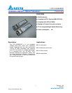

LCP-10G3B4EDR
DELTA ELECTRONICS, INC.
6 Revision: 0B
2008/9/5
www.deltaww.com
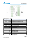
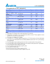
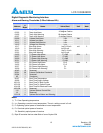
Note:
1. The module signal ground pins, VeeR and VeeT, shall be isolated from the module case.
2. This pin is an open collector/drain output pin and shall be pulled up with 4.7k-10k ohms to Host_Vcc
on the host board. Pull ups can be connected to multiple power supplies, however the host board
design shall ensure that no module pin has voltage exceeding module VccT/R + 0.5V.
3. This pin is an open collector/drain input pin and shall be pulled up with 4.7k-10k ohms to VccT in the
Module.
4. This pin shall be pulled up with 4.7k-10k ohms to Host_Vcc on the host board.
Low speed electrical control pins and 2-wire interface
In addition to the 2-wire serial interface, the SFP+ module has the following low speed pins for control and
status:
‧ TX_Fault
‧ TX_Disable
‧ RS0/RS1
‧ MOD_ABS
‧ RX_LOS
1 TX_Fault
.TX_Fault is a module output pin that when High, indicates that the module transmitter has detected a fault
condition related to laser operation or safety.
The TX_Fault output pin is an open drain/collector and must be pulled p to the Host_Vcc with 4.7k-10k
ohms on the host board
2 TX_Disable
TX_Disable is a module input pin. When TX_Disable is asserted High or Left open, the SFP+ module
transmitter output must be turned off. The TX_DIS pin must be pulled up to VccT in the SFP+ module..
3 RS0/RS1
RS0 and RS1 are module input rate select pins and are pulled low to VeeT with a > 30kΩ resistor in the
module. RS0 is an input hardware pin which optionally selects the optical receive data path rate coverage
for an SFP+ module. RS1 is an input hardware pin which optionally selects the optical transmit path data
rate coverage for an SFP+ module. RS1 is commonly connected to VeeT or VeeR in the legacy SFP
modules. The host needs to ensure that it will not be damaged if this pin is connected to VeeT or VeeR in
the module.