


LCP-1250RJ3SR-S
DELTA ELECTRONICS, INC.
5
Oct. 17. 2007 Rev. 1.02
www.deltaww.com
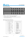
Notes:
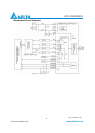
1) TX Fault is not supported and tied to ground.
2) TX disable is an input that is used to reset the chip of Gigabit Ethernet PHY inside the copper SFP. It is pulled
up within the module with a 4.7 – 10 K resistor.
Low (0 – 0.8V): Transmitter on
(>0.8, < 2.0V): Undefined
High (2.0 – 3.465V): Transmitter Disabled
Open: Transmitter Disabled
3) These are the module definition pins. They should be pulled up with a 4.7K – 10K resistor on the host board.
The pull-up voltage shall be VccT or VccR. MOD-DEF 0 is grounded in the module to indicate that the module is
present. MOD-DEF 1 and MOD-DEF 2 are the clock and data lines of the two-wire serial interface, respectively.
4) LOS (Loss of Signal) is not supported and tied to ground.
5) VeeR and VeeT are internally connected within the copper SFP.
6) RD+ and RD- are the received differential outputs, and they are AC-coupled 100 differential lines that should be
terminated with 100 (differential) at user’s SERDES. The AC coupling is done inside the copper SFP and thus
not required on the host board. The differential voltage swing will be between 250mV and 625 mV, while properly
terminated.
7) VccR and VccT are the receiver and transmitter power supplies, and they are internally connected within the
copper SFP. The power rail is defined as 3.3V ±5% at the SFP connector pin.
8) TD+ and TD- are the transmitted differential inputs, and they are terminated with 100 differential load
inside the module. The AC coupling is done inside the module, and thus not required on the host
board.