


NC12S15A_01102008
8
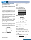
The NC06/NC15/NC20 module has a trim range of 0.9V
to 5.0V. The trim resistor equation for the NC6A/NC15A/
NC20A is :
FEATURES DESCRIPTIONS (CON.)
Input Under-Voltage Lockout
9.0
1170
)(
−
=Ω
Vout
Rs
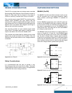
The input under-voltage lockout prevents the converte
r
from being damaged while operating when the inpu
t
voltage is too low. The lockout occurs between 7.0V to
8.0V.
Vout is the output voltage setpoint
Rs is the resistance between Trim and Ground
Rs values should not be less than 280Ω
Over-Current and Short-Circuit Protection
Output Voltage Rs (Ω)
The NC series modules have non-latching over-curren
t
and short-circuit protection circuitry. When over curren
t
condition occurs, the module goes into the non-latching
hiccup mode. When the over-current condition is
removed, the module will resume normal operation.
OPEN +0.9 V
3.92K +1.2 V
+1.5 V 1.96K
+1.8 V 1.3K
+2.5 V 732
A
n over current condition is detected by measuring the
voltage drop across the high-side MOSFET. The voltage
drop across the MOSFET is also a function of the
MOSFET’s Rds(on). Rds(on) is affected by temperature,
therefore ambient temperature will affect the current limit
inception point. Please see the electrical characteristics
for details of the OCP function.
+3.3 V 487
287 +5.0 V
Figure 28: Typical trim resistor values
NC6A/15A/20A
Vout
Ground
Trim
Enable
Ground
Vin
1.3K
Rt
Rs
Vt
The detection of the Rds(on) of the high side MOSFE
T
also acts as an over temperature protection since high
temperature will cause the Rds(on) of the MOSFET to
increase, eventually triggering over-current protection.
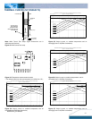
Output Voltage Programming
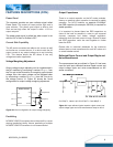
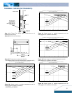
Figure 29: Output voltage trim with voltage source
The output voltage of the NC series is trimmable by
connecting an external resistor between the trim pin and
To use voltage trim, the trim equation for the
NC6A/NC15A/ NC20A is (please refer to Fig. 29) :
output ground as shown Figure 27 and the typical trim
resistor values are shown in Figure 28. The output can
also be set by an external voltage connected to trim pin as
shown in Figure 29.
)9.0(17.1
)17.13.1(
)(
−−
−
=Ω
VoutRs
VtRs
kRt
NC6A/15A/20A
Rs
Vout
Ground
Trim
Enable
Ground
Vin
Vout is the desired output voltage
Vt is the external trim voltage
Rs is the resistance between Trim and Ground (in KΩ)
Rt is the resistor to be defined with the trim voltage (in KΩ)
Below is an example about using this voltage trim
equation :
Figure 27: Trimming Output Voltage
Example:
If Vt = 1.25V, desired Vout = 2.5V and Rs = 0.715KΩ
Ω=
−−
−
=Ω K
VoutRs
VtRs
KRt 51.12
)9.0(17.1
)17.13.1(
)(