


DS_NC12S30A_05222008
6
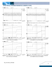
ELECTRICAL CHARACTERISTICS CURVES (CON.)
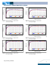
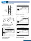
Figure 19: Typical transient response to step load change at
10A/μS from 75% to 50% of Io, max at 12Vin, 1.2V out (Cout =
1uF ceramic, 10μF tantalum)
Figure 20: Typical transient response to step load change at
10A/μS from 75% to 50% of Io, max at 12Vin, 1.5V out (Cout =
1uF ceramic, 10μF tantalum)
Figure 21: Typical transient response to step load change at
10A/μS from 75% to 50% of Io, max at 12Vin, 1.8V out (Cout =
1uF ceramic, 10μF tantalum)
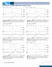
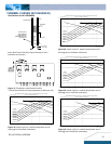
Figure 22: Typical transient response to step load change at
10A/μS from 75% to 50% of Io, max at 12Vin, 2.5V out (Cout =
1uF ceramic, 10μF tantalum)
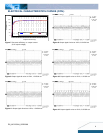
Figure 23: Typical transient response to step load change at
10A/μS from 75% to 50% of Io, max at 12Vin, 3.3V out (Cout =
1uF ceramic, 10μF tantalum)
Figure 24: Typical transient response to step load change at
10A/μS from 75% to 50% of Io, max at 12Vin, 5.0V out (Cout =
1uF ceramic, 10μF tantalum)