


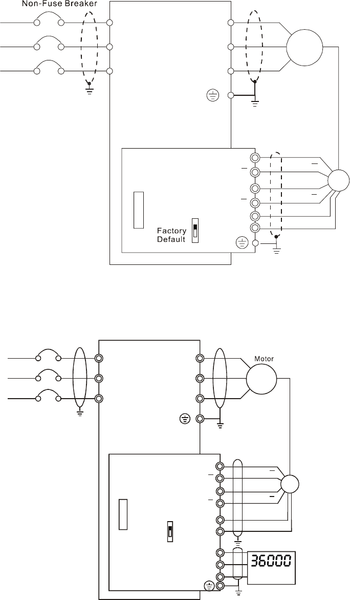
2
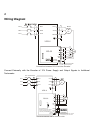
Wiring Diagram
NFB
R/L1
S/L2
T/L3
U/T1
V/T2
W/T3
M
3~
Motor
PG
A
B
12V
0V
PG-03
VFD-V
+12V
GND
OC
TP
Connection between PG-03 and the Encoder
*
Specification of the Encoder
is of the 12V/OC Output
A
B
A
B
A
B
Shield
Terminal
R/L1
S/L2
T/L3
Connect Externally with the Encoder of 12V Power Supply and Output Signals to Additional
Tachometer
Non-Fuse Breaker
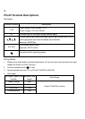
NFB
R/L1
S/L2
T/L3
U/T1
V/T2
W/T3
M
3~
A
B
12V
0V
PG-03
VFD-V
GND
A
B
OC
TP
Connection between PG-03 and the Encoder
A/O
B/O
RPM Meter
*
Specification of the
Encoder is of 12V/OC output,
which could also connect
externally with the RPM wire
*
Power of the should
be supplied by the customers
RPM meter
0V
A
B
A
B
PG
Shield
Terminal
R/L1
S/L2
T/L3