


4
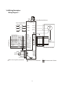
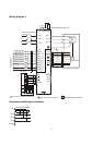
Wiring Diagram 2
FWD
REV
Mi1
Mi2
Mi3
Mi4
Mi6
Mi5
DCM
24V
FWD/STOP
REV/STOP
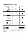
Multi-step2
Multi-step3
Multi-step4
Digital common
R/L1
S/L2
T/L3
Non-Fuse breaker
NFB
R
S
T
+1
+2/B1
B2
U/T1
V/T2
W/T3
M
3~
Braking Resistor(Option)
Motor
Multi-function input terminals
Factory Default
Jumper
Reset
E.F.
-
U
W
V
VP
DCM
A1
A1
B1
B1
Z1
Z1
PG
DCM
A2
A2
B2
B2
VP
DCM
A/O
B/O
Z/O
Multi-step1
Line driver encoder
Line driver
Main circuit (power) terminals
Control circuit terminals
Shielded leads & Cable
EH-PLC
Y0
Y0
Y1
Y1
Y0
Y0
Y1
Y1
Phase difference
90
o
COM
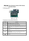
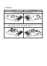
Recommended Wiring for Resistors
VP
DCM
A/O
B/O
Z/O
330
330 330
Pull High Resistor