


DS_Q48SP12017_05302008
5
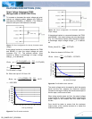
ELECTRICAL CHARACTERISTICS CURVES
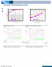
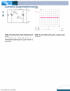
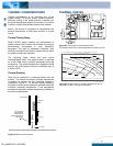
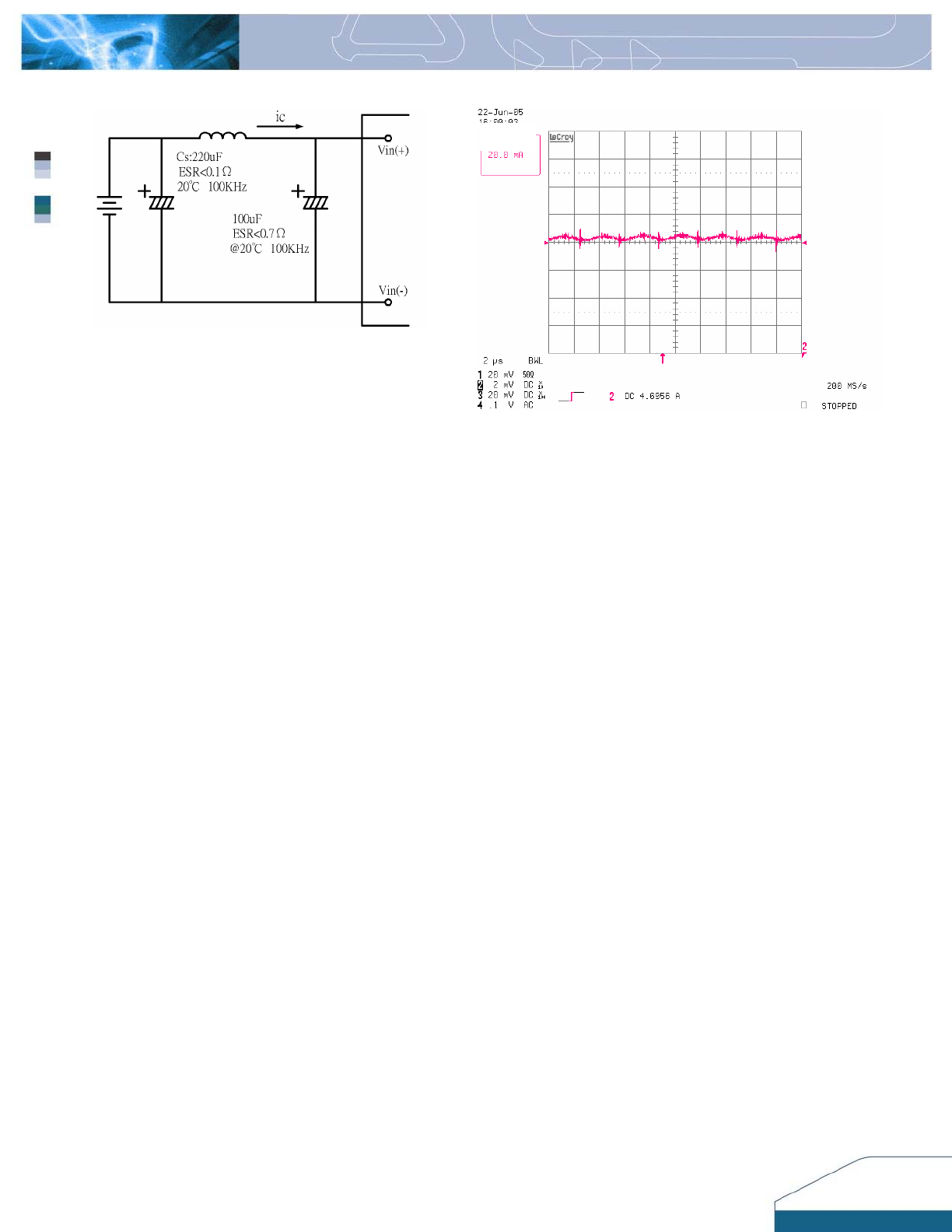
Figure 9: Test set-up diagram showing measurement points
for Input Terminal Ripple Current and Input Reflected Ripple
Current.
Note: Measured input reflected-ripple current with a
simulated source Inductance (L
TEST
)
of 12 μH. Capacitor Cs
offset possible battery impedance. Measure current as
shown above.
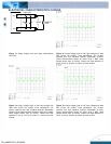
Figure 10: Input reflected ripple current, i
c
through a 12µH
source inductor at nominal input voltage and rated load current
(20 mA/div).