


4
7.0 Test Set-Up
7.1 Initial Set-Up
1) Examine the part number of the power module to determine of the unit is defined
for positive or negative logic enable as follows:
S48SS3R304NR would denote negative logic, while S48SS3R304PR would
denote positive logic (S48SS only).
2) If the power module has positive logic, switching SW1 to position HI or floating will
enable the power converter. Switching SW1 to position Low will disable the power
converter.
3) If the power module has negative logic, switching SW1 to position Low will enable
the power converter. Switching SW1 to position HI or floating will disable the power
converter.
4) Multimeters (1) Ampere / Autorange
Multimeters (2 and 3) Voltage / Autorange
5) Scope
Timebase 10 mS
Trigger Auto
Channel (1)
Volts / Div 10V
Coupling DC
Channel (2)
Volts / Div 1V
Coupling DC
6) Electronic Load
Turn on the Electronic Load and adjust the current level. The total output current is
4.5A (15W) for the S48SR power module and 4.5A (15W) for the S48SS power
module. Ensure the output load does not exceed the recommended maximum
current.
7) SW2 is used for trimming the output voltage. Turn SW2 to the OFF position if the
function is not being used. Turn SW2 to the UP position if trimming up is required.
Turn SW2 to the DOWN position if trimming down is required.
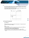
7.2 Initial Power Up
1) Turn the Power Supply on and increase the input voltage (use DVM2 to monitor the
voltage) until it reaches 48V (or the desired value).
2) Toggle SW1 to the appropriate logic position to turn the power module on (S48SS
only).
3) The converter is now operating, which can be verified by observing the DVM3
(approximately 3.3V.) and Channel 2 of the oscilloscope (+3.3V output).