


DS_E48SB12020_05222008
7
DESIGN CONSIDERATIONS
Input Source Impedance
The impedance of the input source connecting to the
DC/DC power modules will interact with the modules
and affect the stability. A low ac-impedance input source
is recommended. If the source inductance is more than
a few μH, we advise adding a 33 to 220μF electrolytic
capacitor (ESR < 0.5 Ω at 100 kHz) mounted close to
the input of the module to improve the stability.
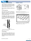
Layout and EMC Considerations
Delta’s DC/DC power modules are designed to operate
in a wide variety of systems and applications. For design
assistance with EMC compliance and related PWB
layout issues, please contact Delta’s technical support
team. An external input filter module is available for
easier EMC compliance design. Below is the example of
using Delta latest FL75L10 A input filter tested with
E48SB12020 to meet class B in CISSPR 22.
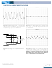
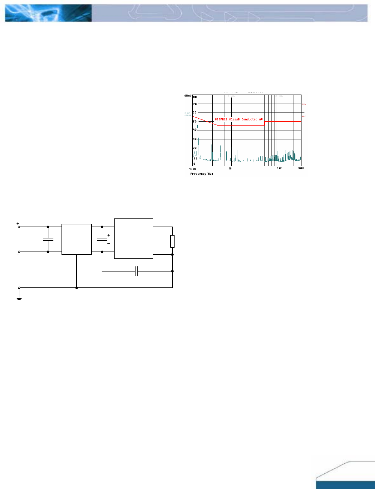
Schematic and Components List
C3
E48SB12020
Series
C1C2
FL75L10 A
Load
Vin
C1 is 100uF/100V, low ESR Aluminum cap;
C2 is 2.2uF ceramic cap;
C3 is 4.7nF ceramic capacitor;
FL75L10 A is Delta input EMI filter module.
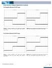
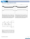
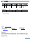
Test Result
Test result is in compliance with CISPR 22 class B, which
is shown as below:
Vin=48V, Io=20A, average mode
Soldering and Cleaning Considerations
Post solder cleaning is usually the final board assembly
process before the board or system undergoes electrical
testing. Inadequate cleaning and/or drying may lower the
reliability of a power module and severely affect the
finished circuit board assembly test. Adequate cleaning
and/or drying is especially important for un-encapsulated
and/or open frame type power modules. For assistance
on appropriate soldering and cleaning procedures,
please contact Delta’s technical support team.
FEATURES DESCRIPTIONS
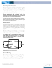
Over-Current Protection
The modules include an internal output over-current
protection circuit, which will endure current limiting for
an unlimited duration during output overload. If the
output current exceeds the OCP set point, the modules
will automatically shut down, and enter in hiccup mode
or latch mode, which is optional.
For hiccup mode, the module will try to restart after
shutdown. If the overload condition still exists, the
module will shut down again. This restart trial will
continue until the overload condition is corrected.
For latch mode, the module will latch off once it
shutdown. The latch is reset by either cycling the input
power or by toggling the on/off signal for one second.