


3 Please read this instruction carefully before use.
3
Switch off the power before wiring.
3 The display panel of TP02 series is waterproof. But please prevent grease, corrosive liquids and sharp objects from
contacting the TP02 series.
3 The TP02 series require 24VDC input power.
DO NOT connect input AC power supply to any of the RS-485
communication port; otherwise serious damage may occur. Check all the wiring again before switching
on the power.
3
DO NOT touch any terminal when the power is switched on. DO NOT touch any internal circuit in 1
minute after the power is switched off.
3
Make sure the groud terminal is correctly grounded in order to prevent electromagnetic
interference.
3
Please use the fixed support accessory which is packed together with the product provided by Delta. DO
NOT tighten the screws out of the normal torque specifications; otherwise serious damage may occur.
X Introduction
1.1 Model Explanation
Thank you for choosing Delta TP Series. TP02G-AS1 has the features of high resolution 160×32 dots. It provides
multilingual display and two built-in communication ports, one is for RS-232 and the other is for RS-485. RS-232
and RS-485 can be used simultaneously. Besides, it also supports communication and alarm LED indicators. The
user can purchase program copy card (optional) to copy settings and programs quickly and save download time.
Nameplate Explanation
MODEL :
POWER INPUT :
TP02GAS1W6050004
VX.XX
TP02G-AS1
24Vdc 3W
DELTA ELECTRONICS, INC MADE IN XXXXXXX
Production model
Power input spec.
Barcode and
serial number
Version
NOTE: The words of “MADE IN XXXXX” will be different due to the manufacturing location. Please refer to the actual product
for exact description.
Model / Serial No. Explanation
TP 02 G AS 1 -
Reserved
Reserved
T: Text mode
G: Graphic mode
LCD Spec.
Series name
TP02GAS 1 W 6 05 0004
Production serial number
Production weeks
Production year (2006)
Production plant
Version
Production model
(W: Wuijang; T: Taoyuan)
1.2 Product Outline
Displaying Area
RS-232 LED Indicator
RS-485 LED Indicator
Escape / Exit Key
Alarm LED Indicator
Function Keys
Arrow Keys
Enter Key
1.3 Panel Function Explanation
PANEL COMPONENT EXPLANATION
Alarm LED Indicator
(RED)
Status 1: When power is on, LED will blink slowly for three times.
Status 2: When there is an abnormal situation, LED will blink quickly along with
an alarm sound.
RS-232 LED Indicator
(Yellow)
LED will blink when transmits program and communicates via RS-232.
RS-485 LED Indicator
(Green)
LED will blink when communicates via RS-485.
Displaying Area Liquid Crystal Module display area. It is used to display current program status.
PANEL COMPONENT EXPLANATION
Escape / Exit Key It is used to cancel an incorrect input, or to exit a programming step.
Enter Key It is used to input a value or accept a programming command.
Arrow Keys
UP / Pg Up: It is used to increase the value or move up one page.
Pg Dn / DOWN: It is used to decrease the value or move down one page.
Left: This key is left direction key and it can be used to select the position of the
value.
Right: This key is right direction key and it can be used to select the position of
the value.
Function Keys
F0 / 0: It is used as a constant 0, or the user can define it as function F0.
F1 / 1: It is used as a constant 1, or the user can define it as function F1.
F2 / 2: It is used as a constant 2, or the user can define it as function F2.
F3 / 3: It is used as a constant 3, or the user can define it as function F3.
F4 / 4: It is used as a constant 4, or the user can define it as function F4.
F5 / 5: It is used as a constant 5, or the user can define it as function F5.
F6 / 6: It is used as a constant 6, or the user can define it as function F6.
F7 / 7: It is used as a constant 7, or the user can define it as function F7.
F8 / 8: It is used as a constant 8, or the user can define it as function F8.
F9 / 9: It is used as a constant 9, or the user can define it as function F9.
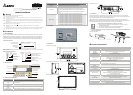
1.4 Back Panel
RS-232
Extension port
5 PIN terminal / Wire gauge: 12-24 AWG / Torque: 4.5 lb.-inch
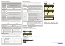
1.5 Dimension
Front panel (unit: mm [inch])
Right side diagram (unit: mm [inch]) Back panel
Mounting dimension (unit: mm [inch])
Thickness Range 0.5~9mm
135~136.5[5.31~5.37]
85
[3.35]
Vertical view (Unit: mm)
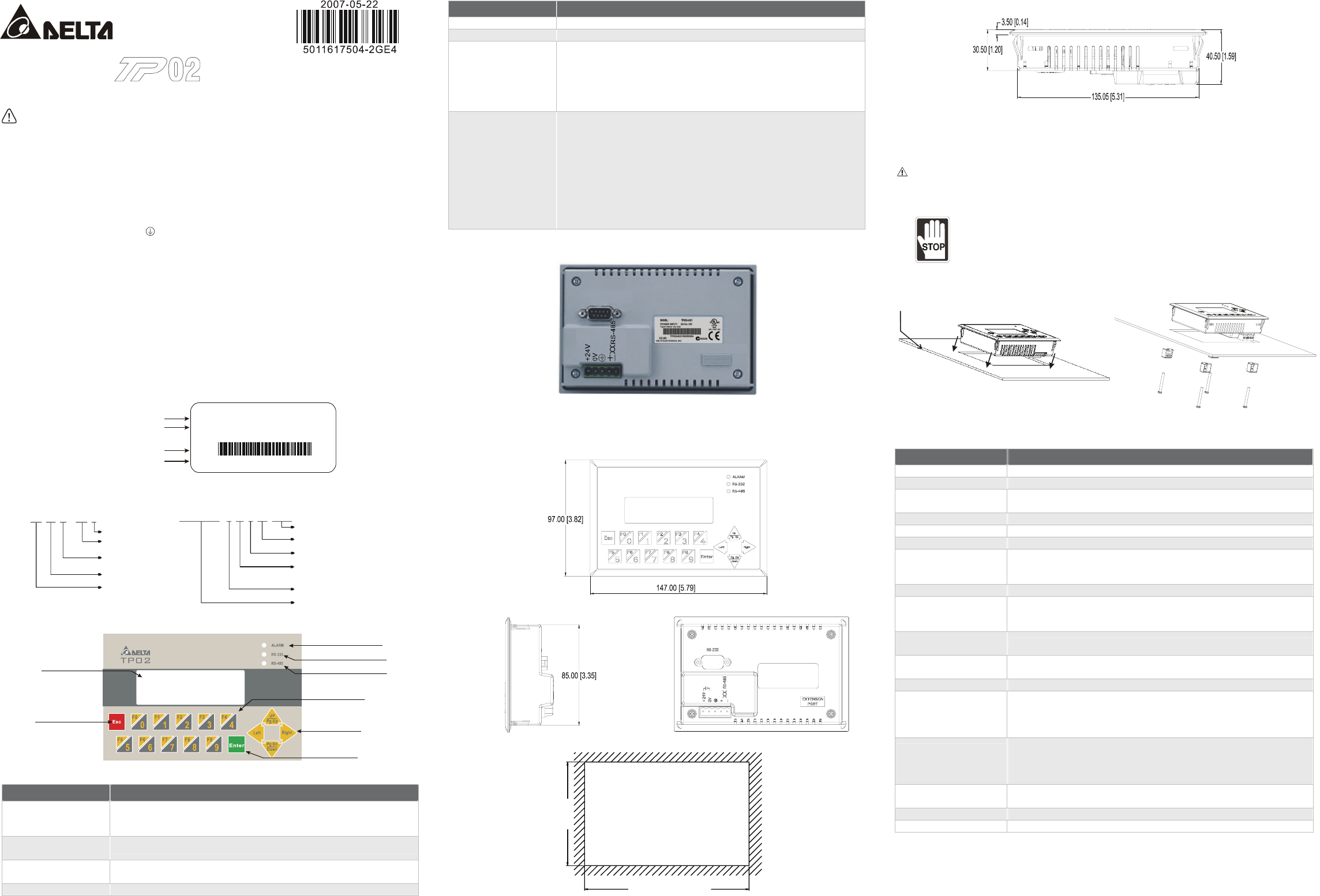
1.6 Installation
Please insert TP02 series to the opening hole of panel and tighten the screws. However, if a firm mounting TP02
series to the panel is needed, please use the mounting fixed support accessory which is packed together with TP02
series, then insert the fixed support in the back and tighten the screws.
If the fixed support is not installed well, Delta will not guarantee the waterproof function. The screw torque
should be 4-5(kg-cm). DO NOT exceed this specification when tightening the screws; otherwise TP02 series may be
damaged. Please leave sufficient space (more than 50mm) around the unit for heat dissipation.
Do not install and mount TP02 series in the following environment.
h A location subjected to Airborne dust, metallic particles, oil and smoke, corrosive or
flammable gases and liquids.
h A location where temperature and humidity will exceed specifications.
h A location where vibration and shock will exceed specifications.
The flat surface should be a UL Type 4 "Indoor Use Only" enclosure or equivalent (IP65 / NEMA4). Please
refer to the figures below.
Thickness: 0.5~9.0mm
Y Function Specifications
ITEM TP02G-AS1
Screen Type STN-LCD
Display Color Monochromatic
Backlight
The back-light automatic turn off time is 1 ~ 99 minutes (0 = do not turn off)
(The back-light life is about 50 thousand hours at 25°C)
Resolution 160 x 32 dots
Display Range (W) x (H) = 72 x 22 (unit: mm)
Contrast Adjustment 15 levels of adjustment
Language / Font
ASCII: Alphanumeric (including European characters)
Taiwan: (Big 5 codes) Traditional Chinese Fonts
China: (GB2324-80 codes) Simplified Chinese Fonts
Font Size ASCII: 5 × 8, 8 × 8, 8 × 12, 8 × 16
Alarm LED Indicator (RED)
1. Power on indication (Blink for three times)
2. Communication error alarm
3. Special indication by user programming
RS-232 LED Indicator
(Yellow)
It will blink when transmitting program and communicating by using RS-232.
RS-485 LED Indicator
(Green)
It will blink when communicating by using RS-485.
Program Memory 256KB flash memory
Serial Communication Port
RS-232 (COM1)
Unsynchronized transmission method: RS-232
Data length: 7 or 8 bits, Stop bits: 1 or 2 bits
Parity: None/Odd/Even, Transmission speed: 4,800bps ~115,200bps
RS-232: 9 PIN D-SUB male
Extension Communication
Port
RS-485 (COM2)
Unsynchronized transmission method: RS-485
Data length: 7 or 8 bits, Stop bits: 1 or 2 bits
Parity: None/Odd/Even, Transmission speed: 4,800bps ~115,200bps
RS-485: 5 PIN removal terminal
Extension Interface 1. Update firmware version
2. The slot for program copy card
Battery Cover DC 3V battery for HMI
5 PIN Removal Terminal Include DC 24V input and RS-485 communication input
http://www.delta.com.tw/industrialautomation/
Terminal Panels Series
!
Instruction Sheet
Warning