Dialogic
®
D/82JCT-U
PBX Integration Board
Quick Install Card
Part Number: 64-0089-02
Copyright © 2000-2007
Dialogic Corporation. All
rights reserved.
Before You Begin
Protecting the Board from Damage
CAUTION: All computer boards are sensitive to
electrostatic discharge (“ESD”). Handle all static-
sensitive boards and components at a static-safe
work area,
and observe anti-static precautions at all times.
If you are not familiar with ESD safety precautions,
visit
http://www.dialogic.com/support/hwinstall to learn
more.
Unpacking the Board
Unpack the Dialogic
®
D/82JCT-U PBX Integration
board (“board”) according to the following steps:
1. Prepare a static-safeguarded work area.
2. Carefully remove the board from the shipping
carton and anti-static packaging. Handle the
board by the edges and avoid touching the
board’s components.
3. Lay the board on the static-dissipative work
surface.
Note: Place boards in static-shielding bags when
carrying boards from station to station.
CAUTION: Do not remove the board from the anti-
static packaging until you are ready to install it.
Observe proper anti-static precautions at all times.
Configuring the Hardware
The Dialogic
®
D/82JCT-U board is a PCI form factor
board that uses hardware auto-configuration for IRQ
and memory address. It allows you to use the factory
default hardware settings for quick installation and
operation. However, you should review the following
information to determine if any of the optional
configuration items apply to your system.
Setting the Board Identification Number
When you start a Dialogic
®
board, each board is
assigned a Board ID number for identification and use
by the application program.
All Dialogic
®
PCI boards with a rotary switch can
share the factory default switch setting and Board ID
of 0. To give a PCI board with a rotary switch a Board
ID other than 0, the rotary switch is set to the desired
number. Because the Dialogic
®
D/82JCT-U board has
no rotary switch, the Dialogic
®
Configuration Manager
(DCM) software that is provided with the board
automatically assigns Board IDs, beginning with 0,
unless there are other PCI boards with a rotary switch
settings of 0, 1, 2, etc. In that case, DCM assigns the
first available Board ID not in use.
The Board ID of the Dialogic
®
D/82JCT-U can only be
changed by using DCM. See the DCM help files for
more information about changing Board IDs.
Note: If you add PCI boards with rotary switches to
your system after Dialogic
®
D/82JCT-U boards have
been assigned, boards may share the same ID,
depending on the rotary switch settings of the new
boards. For instance, if DCM has assigned Board IDs
01, 02, and 03 to existing Dialogic
®
D/82JCT-U
boards, and then the rotary switches on three new
boards are set to 1, 2, and 3, the Dialogic
®
D/82JCT-U
and new boards will share Board IDs 01, 02, and 03.
The Dialogic
®
D/82JCT-U Board ID appears on the 2-
character LED display on the rear bracket of the
board, along with error codes, when appropriate.
Display Meaning
00-xx Board ID (in hexadecimal)
88 PCI Bus reset active
D0 Front-end download or initialization
failed
E1-E8 Error on PBX port 0-7 (channel 1-8)
Following download, the Board ID is continuously
displayed on the LED unless a communications error
is experienced on one or more of the PBX ports.
When errors are present, they are displayed for two
seconds, alternating with the Board ID for two
seconds.
CT Bus Termination
Jumpers are used to terminate signals on the CT Bus.
These settings apply to boards located at physical
ends of the bus. For CT Bus or SCbus, both
CT_C8_(A&B) and CT_FRAME_(A&B) are terminated
using pins 1 and 2 of the P8 termination jumpers. For
MVIP, C-2 and C-4* are terminated using pins 3 and 4
of the P8 termination jumpers.
Note: Only the two boards at the ends of the CT Bus
ribbon cable must have their terminations enabled. All
other boards must not have the jumper clips installed.
Installing the Board
1. Working with your computer at a static-safe work
area, switch off the power and disconnect all
power cords from the electrical outlets.
2. Remove the chassis cover.
3. Select an empty PCI expansion bus slot and
remove the slot’s retaining screw and access
cover plate.
4. If you are not installing your board in an ISA form
factor PCI slot, remove the ISA edge retainer
bracket from the board.
5. Using the slot’s board guides, insert the edge
connector of the board into the bus slot. Press
firmly until the board is securely seated in the slot.
6. Replace and tighten the retaining screw to secure
the board firmly in the chassis slot. If the screw is
not installed, attaching a CT Bus cable can unseat
the board from the slot.
Installing the PCI Board
ISA Slot
PCI Slot
PCI
Board
Computer
Chassis
Remove
Cover
Plate
7. Repeat steps 3–6 for each board you are
installing.
Connecting the CT Bus Cable
Note: If you are using the Dialogic
®
D/82JCT-U in
"stand-alone" mode, where the application does not
use time-slot routing, you do not need to connect a
CT Bus cable and you may skip the instructions in this
section. You only need to perform this part of the
installation if your system uses multiple boards and
controls resources on the boards through time-slot
routing.
The Dialogic
®
D/82JCT-U connects to other boards
via the H.100-compliant Computer Telephony bus (CT
Bus) using an optional CT Bus cable.
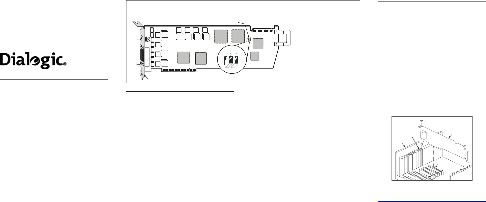
Physical Description
Board ID
Display
J1
PCI bus connector
Rear bracket
CT Bus connector
P8
Pin 4
Pin 3
Pin 2
Pin 1
P8 Detail
J1: 36-position mini-D plug
connector
P8: CT Bus termination jumpers.
Bus signals are terminated when
jumper clip is installed over
indicated pins
Note: Bus signals must be
terminated only on boards at each
end of the CT Bus cable.
Pins 1 & 2—CT Bus/SCbus
termination
Pins 3 & 4—MVIP Bus termination
CT Bus connector: ECTF H.100-
compliant CT Bus edge connector


