


Factory default is unterminated (jumper clip
removed).
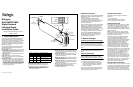
The following figure shows the pair of pins used for
CT Bus termination. Refer to P5 in the Physical
Layout figure for the location of the jumper block.
Setting Power-off Default Front End
Loopback
When the system shuts down (powers off), the
board enables analog loopback to the connected
trunk line(s). Factory default setting is enabled for
each trunk (jumper clips are installed). To disable,
remove the pair of jumper clips for the desired
trunk(s).
The following table lists each pair of jumpers and the
corresponding trunk. Refer to the Physical Layout
figure for the location of the jumpers.
Setting Boot Up Default Front End
Loopback
When the system is started or restarted, the board
enables analog loopback to the connected trunk
line(s) and provides digital loopback to the board.
Factory default setting is enabled (jumper clip is
removed). To disable, install the jumper clip. Refer to
JP5 in the Physical Layout figure.
3. Installing the Board
CAUTION: These procedures assume familiarity
with the general terminology associated with
electronic equipment and with the safety practices
and regulatory compliance required for using and
Trunk Jumper pair
1 JP3X11 and JP4X11
2 JP3X12 and JP4X12
3 JP3X13 and JP4X13
4 JP3X14 and JP4X14
CT Bus
Termination
CT Bus
Connector
modifying electronic equipment.
These procedures should be performed only by
qualified technical personnel.
WARNING! Unplug the equipment before
performing the procedures described here.
Failure to disconnect the power before you open
the chassis can result in personal injury. Ensure
that the system is disconnected from its power
source and from all telecommunications links,
networks, or modem lines whenever the chassis
cover is removed. Do not operate the system
with the cover removed.
CAUTION: To avoid possible damage to the board,
remove power from the computer before beginning
installation. Observe proper anti-static precautions
at all times while handling and installing the board.
Note: It is recommended that you install the
hardware before installing the software.
Install the board as follows:
1. With your computer at a static-safe work area,
switch off the power and disconnect the power
cord.
2. Remove the computer cover.
3. Select an empty PCI expansion bus slot and
remove the slot’s retaining screw and coverplate.
4. If you are installing your board in an ISA form
factor PCI slot, optionally install an ISA edge
retainer on the board.
5. Using the slot’s board guides, insert the edge
connector of the board into the bus slot. Press
firmly until the board is securely seated in the
slot.
6. Replace and tighten the retaining screw to
secure the board firmly in the bus slot.
7. Repeat steps 3–6 for each board you are
installing.
8. If appropriate, use an optional CT Bus cable to
connect the board(s) you are installing to other
boards in the system. To preserve the electrical
integrity of the CT Bus, use a CT Bus cable with
the appropriate number of connectors (“drops”).
It is recommended that no more than two
connectors at either end of the cable be left
unused. For boards located at each end of the
CT Bus cable, be sure to set bus termination
appropriately as described in the Setting CT Bus
Termination section.
9. Replace the computer cover when finished and
reconnect the power cord.
10. Turn on the power to the computer.
Note: If your BIOS is set to use Plug and Play
technology and there are ISA boards in your system,
an IRQ conflict can occur if your PCI board is
assigned the same IRQ as an ISA board. This can
cause the machine to stop responding. To prevent
this conflict, enter the BIOS and reserve the
appropriate IRQs (those used by your ISA boards)
for ISA use only.
4. Connecting to External
Equipment
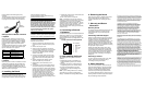
Connect the RJ-48C jack on the board bracket to the
switch using a digital T1 or E1 crossover cable. If
you are building your own cable, you should be
familiar with the connector pin designations for the
RJ-48C jack.
RJ-48C Connector Pin Designations
5. After Installing the Board
After installing the board, proceed with these
activities:
■
Installing the software, as described in the
software installation guide for your software
release
■
Configuring the software, as described in the
configuration guide for your software release
■
For technical specifications and product
information go to: http://www.dialogic.com/
products.htm.
Note: If you are adding hardware to an existing
system, you do not need to uninstall existing
Dialogic
®
Host Media Processing (HMP) software.
RCV_RING
RCV_TIP
N/C
XMIT_RING
XMIT_TIP
N/C
N/C
N/C
1
2
3
4
5
6
7
8
Pin
Pin 1
Function
6. Removing the Board
Removal of the board is a straightforward process.
Remove the board using the reverse of the
procedure described in the Installing the Board
section.
7. Warranty and Return
Information
Warranty Period
For specific warranty information for this board, refer
to the Warranty section of the Products page,
located at this URL: http://www.dialogic.com/
warranties/.
Contacting Technical Support
Dialogic provides technical support for its products
through a network of value added distributors who
are trained to answer technical questions on
installing and configuring Dialogic® products. If you
are unsure how to contact your support channel,
please call Dialogic in the United States at 973-967-
6600 (9am-5pm EST) and we will assist in obtaining
the appropriate support channel.
Outside the United States please refer to http://
www.dialogic.com/support/contact to obtain local
contact information. Dialogic also provides direct
support via Dialogic
®
Pro™ Services agreements.
For more details of direct support from Dialogic
please refer to:http://www.dialogic.com/support/
Dialogic Pro
Returning a Product
To return a board for warranty repair or any other
returns, please refer to the following: http://
www.dialogic.com/support/hwfaults.
8. Sales Assistance
If you have a sales question, please contact your
local Sales Representative or the Regional Sales
Office for your area. Address, telephone and fax
numbers, are available at the Dialogic website
located at: http://www.dialogic.com/contact.htm.
To purchase Dialogic® products, please refer to the
following website to locate the appropriate supplier:
http://www.dialogic.com/purchase.htm.
All contents of this document are furnished for informational use
only and are subject to change without notice and do not represent
a commitment on the part of Dialogic Corporation or its subsidiaries
(“Dialogic”). Reasonable effort is made to ensure the accuracy of
the information contained in the document. However, Dialogic does
not warrant the accuracy of this information and cannot accept
responsibility for errors, inaccuracies or omissions that may be
contained in this document.
INFORMATION IN THIS DOCUMENT IS PROVIDED IN
CONNECTION WITH DIALOGIC® PRODUCTS. NO LICENSE,
EXPRESS OR IMPLIED, BY ESTOPPEL OR OTHERWISE, TO
ANY INTELLECTUAL PROPERTY RIGHTS IS GRANTED BY
THIS DOCUMENT. EXCEPT AS PROVIDED IN A SIGNED
AGREEMENT BETWEEN YOU AND DIALOGIC, DIALOGIC
ASSUMES NO LIABILITY WHATSOEVER, AND DIALOGIC
DISCLAIMS ANY EXPRESS OR IMPLIED WARRANTY,
RELATING TO SALE AND/OR USE OF DIALOGIC PRODUCTS
INCLUDING LIABILITY OR WARRANTIES RELATING TO
FITNESS FOR A PARTICULAR PURPOSE, MERCHANTABILITY,
OR INFRINGEMENT OF ANY INTELLECTUAL PROPERTY
RIGHT OF A THIRD PARTY.
Dialogic products are not intended for use in medical, life saving,
life sustaining, critical control or safety systems, or in nuclear facility
applications.
It is possible that the use or implementation of any one of the
concepts, applications, or ideas described in this document, in
marketing collateral produced by or on web pages maintained by
Dialogic may infringe one or more patents or other intellectual
property rights owned by third parties. Dialogic does not provide
any intellectual property licenses with the sale of Dialogic products
other than a license to use such product in accordance with
intellectual property owned or validly licensed by Dialogic and no
such licenses are provided except pursuant to a signed agreement
with Dialogic. More detailed information about such intellectual
property is available from Dialogic’s legal department at 9800
Cavendish Blvd., 5th Floor, Montreal, Quebec, Canada H4M 2V9.
Dialogic encourages all users of its products to procure all
necessary intellectual property licenses required to implement
any concepts or applications and does not condone or
encourage any intellectual property infringement and
disclaims any responsibility related thereto. These intellectual
property licenses may differ from country to country and it is
the responsibility of those who develop the concepts or
applications to be aware of and comply with different national
license requirements.
Dialogic, Diva, Eicon, Eicon Networks, Eiconcard, Dialogic Pro and
SIPcontrol, among others, are either registered trademarks or
trademarks of Dialogic. Dialogic's trademarks may be used publicly
only with permission from Dialogic. Such permission may only be
granted by Dialogic’s legal department at 9800 Cavendish Blvd.,
5th Floor, Montreal, Quebec, Canada H4M 2V9. Any authorized
use of Dialogic's trademarks will be subject to full respect of the
trademark guidelines published by Dialogic from time to time and
any use of Dialogic’s trademarks requires proper
acknowledgement. The names of actual companies and products
mentioned herein are the trademarks of their respective owners.