


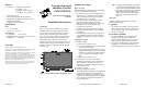

SYNC/570i (PCI) Installation Card SYNC/570i SYNC/570i (PCI) Installation Card SYNC/570i
Cabling Information
The cables included with your adapter are designed
with custom components and cannot be indepen-
dently manufactured. If you require multiple periph-
eral cables of one type, you may order additional
cables from Digi. To extend the length of a Digi
cable, use standard interface cabling between the
end of Digi’s cable and the peripheral.
Interface Pinouts
Each cable provided by Digi has a 26-pin HDD con-
nector on one end, which attaches to a port on the
Universal Interface Card. The other end of the cable
will provide signals according to the interface stan-
dards. The pinout information for each of the cables
follows.
EIA-232, Male DB-25 Connector
V.35, Male 34-pin Connector
X.21, Male DB-15 Connector
EIA-530, Male DB-25 Connector
Re
g
ulatory Notices
Federal Communications Commission (FCC)
Statement
Radio Frequency Interference (RFI) (FCC 15.105)
This device has been tested and found to comply with the limits for Class
B digital devices pursuant to Part 15 Subpart B, of the FCC Rules. These
limits are designed to provide reasonable protection against harmful inter-
ference in a residential environment. This equipment generates, uses, and
can radiate radio frequency energy, and if not installed and used in accor-
dance with the instruction manual, may cause harmful interference to radio
communications. However, there is no guarantee that interference will not
occur in a particular installation. If this equipment does cause harmful
interference to radio or television reception, which can be determined by
turning the equipment off and on, the user is encouraged to try and correct
the interference by one or more of the following measures:
• Reorient or relocate the receiving antenna.
• Increase the separation between the equipment and the receiver.
• Connect the equipment into an outlet on a circuit different from that
to which the receiver is connected.
• Consult the dealer or an experienced radio/TV technician for help.
Labeling Requirements (FCC 15.19)
This device complies with Part 15 of FCC rules. Operation is subject to the
following two conditions: (1) this device may not cause harmful interfer-
ence, and (2) this device must accept any interference received, including
interference that may cause undesired operation.
Modifications (FCC 15.21)
Changes or modifications to this equipment not expressly approved by
Digi may void the user’s authority to operate this equipment.
Declaration Of Conformity
(In accordance with FCC Dockets 96-208 and 95-19)
Manufacturer’s Name:
Digi International
Cor
p
orate Head
q
uarters:
11001 Bren Road East
Minnetonka MN 55343
Manufacturin
g
Head
q
uarters:
10000 West 76th Street
Eden Prairie MN 55344
Digi International declares, that the product:
Product Name:
SYNC/570i PCI
Model Numbers:
50000899-01 used with
63000002, 63000003,
63000004 and/or 63000008
To which this declaration relates, meets the requirements specified by the
Federal Communications Commission as detailed in the following specifi-
cations
• Part 15, Subpart B, for Class B Equipment
• FCC Docket 96-208 as it applies to Class B personal Computers and
Peripherals
The product listed above has been tested at an External Test Laboratory
certified per FCC rules and has been found to meet the FCC, Part 15, Class
B, Emission Limits. Documentation is on file and available from the Digi
Tested to Com
p
l
y
With FCC Standards
FOR HOME OR OFFICE USE
50000899-01 used with
63000002
,
63000003
63000004
,
and/or
63000008
International Homologation Department.
Industry Canada
This Class B digital apparatus meets the requirements of the Canadian
Interference Causing Equipment Regulations.
Cet appareil numérique de la classe B respecte toutes les exigences du
Règlement sur le máteriel brouilleur du Canada.
European EMC Standards
This device meets the following electromagnetic emissions standards:
• EN55022
• EN50082-2
European TTE Standard
This device meets the I-CTR2 standard.
Safety Standards
This device meets the following safety standards:
• UL 1950
• CSA 22.2 No. 950
• EN60950
Pin Description Pin Description
2 TXD 20 DTR
3 RXD 6 DSR
15 TXCIN 8 DCD
17 RXC 24 TXCOUT
4 RTS 22 RI
5 CTS 7 GND
1 and
shell
CGND
Pin Description Pin Description
A CGND R RXD(A)
B GND T RXD(B)
C RTS U TXCLKOUT(A)
D CTS W TXCLKOUT(B)
E DSR V RXCLK(A)
F DCD X RXCLK(B)
H DTR Y TXCLKIN(A)
P TXD(A) AA TXCLKIN(B)
S TXD(B)
Pin Description Pin Description
2 TXD(A) 12 Indicator(B)
9 TXD(B) 6 SETI(A)*
3 Control(A) 13 SETI(B)*
10 Control(B) 7 SETO(A)**
4 RXD(A) 14 SETO(B)**
11 RXD(B) 8 Signal Ground
5 Indicator(A) 1 and
shell
CGND
* SETI=Signal Element Timing In
** SETO=Signal Element Timing Out
Pin Description Pin Description
2 TXD(A) 13 CTS(B)
14 TXD(B) 20 DTE Ready(A)
3 RXD(A) 23 DTE Ready(B)
16 RXD(B) 6 DCE Ready(A)
15 TXCLKIN(A) 22 DCE Ready(B)
12 TXCLKIN(B) 8 RLSD(A)*
17 RXCLK(A) 10 RLSD(B)*
9 RXCLK(B) 24 TXCLKOUT(A)
4 RTS(A) 11 TXCLKOUT(B)
19 RTS(B) 7 Signal Ground
5 CTS(A) 1 and
shell
CGND
* RLSD=Received Line Signal Detector