


Installing the EtherLite Hardware
1. Write the MAC address of the EtherLite module on the following
line. It will be needed during software installation. This address is
printed on a label next to the power plug at the back of the unit.
MAC Address # 00AOE7______________
2. Connect the Ethernet cable to the unit using the RJ-45 jack labeled
10BASE-T or 10/100BASE-T located on the front of the cabinet.
Use the provided straight-through cable to connect the unit to a hub.
Connecting directly to an Ethernet card will require a 10Base-T
crossover cable (not provided). Note that either wiring scheme
requires that the twisted pairs be used for specific pairs of pins: 1&2,
3&6, 4&5, and 7&8.
RJ-45 Pinouts
3. Assign an IP address to the EtherLite module.
You will need to go to the software installation procedures on the
Access Resource CD for information on how to assign an IP address.
Rack Mount Installation
For the EtherLite 32, a rack mount kit is included. The rack mount brack-
ets may be installed at either the front or rear of the unit.
To install each bracket, do the following:
1. Remove the two screws on the side of the cabinet.
CAUTION: To prevent electric shock, do not remove the module
cover. There are no user-serviceable parts inside. Refer
servicing to qualified personnel only.
2. Align the countersunk holes of the bracket with the vacated holes in
the cabinet. Use the countersink screws to fasten the bracket to the
cabinet.
Rack Mount Considerations
When doing a rack mount installation consider the following:
• Cumulative power requirements of the unit and other equipment
installed in the rack. Do not overload rack supply circuits.
• Safety and stability. Always stack the rack from bottom up to ensure
a stable and safe rack.
Note: The EtherLite 32 weighs 5.8 lbs (2.6 kgs).
• Air flow in the rack. Make sure the unit’s ambient temperature does
not exceed 95°F (35°C).
• Grounding. Earth ground the unit reliably to the rack system. The
earth ground connection must be maintained when the supply con-
nection is other than a direct connection to the branch circuit.
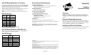
EIA - 232 Connectors
Many EIA-232 serial devices implement their serial ports with DB-25
connectors. The EtherLite units have serial ports implemented with 8-pin
RJ-45 modular jacks, with each signal using EIA-232 voltage levels. The
figures below shows the pinouts of all these connector types.
EIA-232 DTE Pinouts
IMPORTANT: RJ-45 cables designed for other Digi products must not
be used with Digi EtherLite and SCSI Terminal Server products. The
EtherLite RJ-45 pin configuration differs from the configuration of the
RJ-45 connectors used on other Digi products. The table above shows the
different signals, along with the standard DB-25, DB-9 and the EtherLite
8-pin RJ-45 pinout.
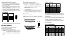
The most convenient method of mating DB-25 and DB-9 serial devices
to your EtherLite Port Server is to use RJ-45 to DB-25 and RJ-45 to DB-
9 adapters. This allows the DTE/DCE selection to occur at the adapter,
while using “straight-through” modular cables. To assure CE
(Conformité Européenne) mark compliance (Europe), all serial cables
must be shielded. The following RJ-45 to DB-25 adapters are available
from Digi International, along with two-meter unshielded straight-
through modular cables:
RJ-45 to DB-25 Adapters
Straight-through Crossover
Pin to Pin Pin to Pin
1 to 1 1 to 3
2 to 2 2 to 6
3 to 3 3 to 1
4 to 4 4 to 4
5 to 5 5 to 5
6 to 6 6 to 2
7 to 7 7 to 7
8 to 8 8 to 8
Pin 1 Pin x
RJ-45 Plug
13
1
14
25
Male DB-25
13
1
14
25
Female DB-25
Pin 1
Pin x
RJ-45 Plug
EtherLite
RJ-45 Pin
Signal DB-25 Pin DB-9 Pin
1 RTS (out) 4 7
2 DSR (in) 6 6
3 DCD (in) 8 1
4 RxD (in) 3 2
5 TxD (out) 2 3
6 GND 7 5
7 DTR (out) 20 4
8 CTS (in) 5 8
P/N 76000450
(DTE to Modems)
P/N 76000451
(DCE to Terminals/Printers)
RJ-45
Jack
Signal
DB-25
Male
RJ-45
Jack
Signal
DB-25
Male
1 RTS 4 1 RTS 5
2 DSR 6 2 n/c 6
3 DCD 8 3 DCD 20
4 RxD 3 4 RxD 2
5 TxD 2 5 TxD 3
6 GND 7 6 GND 7
7 DTR 20 7 DTR 8
8 CTS 5 8 CTS 4