


TransPort
®
WR44 Installation Guide
Page 8
TransPort
®
WR44 Installation Guide
Page 9
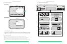
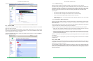
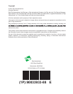
2.2 Front Panel Features
1
10
2
3
4
5
6
7
8
9
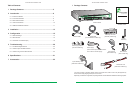
1. USB Host Connector - The USB host connector may be used to connect compatible USB 2.0 client
devices such as memory sticks, and serial adapters. The total current available to power USB devices is
0.5A.
2. LED Status Indicator - POWER - Illuminates steady when power is connected.
3. LED Status Indicator - LAN (0, 1, 2, 3) - Illuminates steady when there is a network connection to the LAN
port and ashes when data is transmitted or received.
4. LED Status Indicator - Wi-Fi -Illuminates steady if Wi-Fi activity is present.
5. LED Status Indicator - SERIAL - Illuminates steady if a terminal is connected to the SERIAL 0 port and the
DTR signal is on. Flashes when data is transmitted or received.
6. LED Status Indicator - LINK - Illuminates steady when a wireless data connection has been established.
7. LED Status Indicator - SIM - Illuminates steady when a valid SIM card is installed.
8. LED Status Indicator - ACT - Flashes to indicate that data is being transferred over the wireless network.
9. LED Status Indicator - SIGNAL.
a) WR44 - G, -E and -U models: signal strengths are as follows:
• 0 LEDs illuminated: < -113 dBm (effectively no signal)
• 1 LED illuminated: >= -112 dBm and <= -87 dBm (weak)
• 2 LEDs illuminated: >= -86 dBm and <= -71 dBm (medium)
• 3 LEDs illuminated: >= -70 dBm and <= -51 dBm (strong)
b) WR44 - C models: signal strengths are as follows:
• 0 LEDs illuminated: < -116 dBm (effectively no signal)
• 1 LED illuminated: >= -115 dBm and <= -104 dBm (weak)
• 2 LEDs illuminated: >= -103 dBm and <= -94 dBm (medium)
• 3 LEDs illuminated: >= -93 dBm and <= -83 dBm (strong)
10. SIM / R-UIM Sockets (SIM card models only) - SIM 1 and SIM 2 are for use with the Subscriber
Identication Module(s) (SIMs) or Removable User Identication Module(s) (R-UIMs).
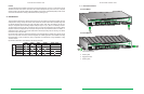
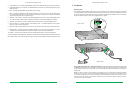
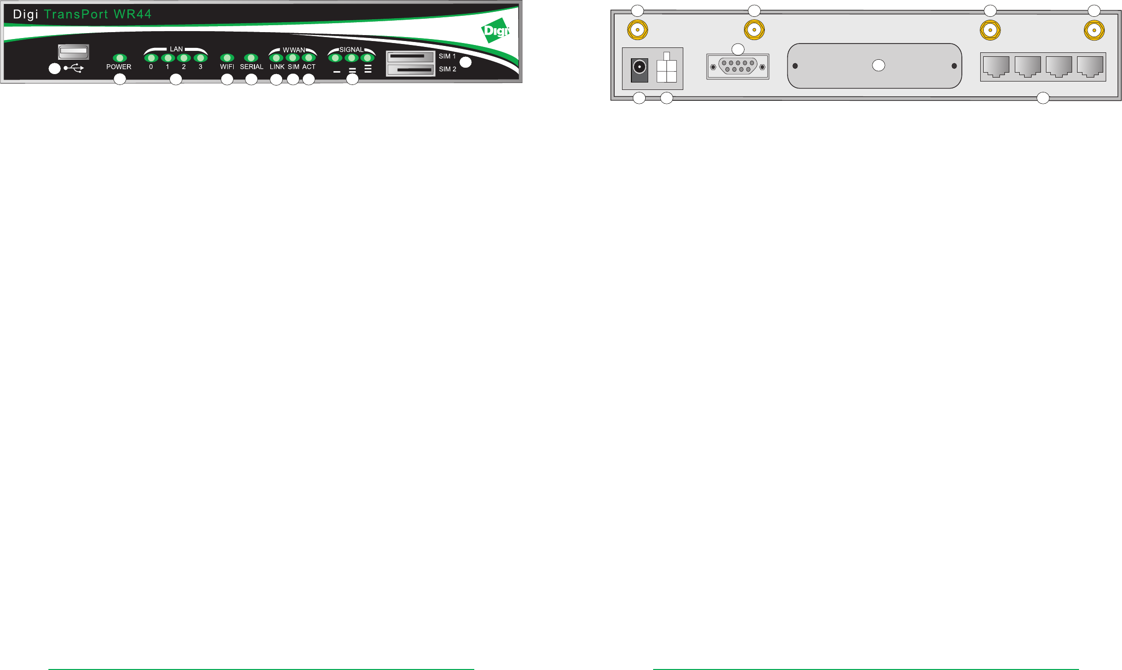
2.3 Rear Panel Features
WWAN PRIMARY WIFI SECONDARY
11-58VDC
1.3A MAX
MAIN
AUX.
WIFI PRIMARYWWAN SECONDARY
LAN3
LAN2 LAN1
LAN0
SERIAL 0
1
7
2 3 4
8
5 6
9
1. Primary Cellular (WWAN) Antenna Connector - This SMA female connector is used to connect the unit’s
primary cellular antenna.
2. Secondary Wi-Fi (WLAN) Antenna Connector (Wi-Fi models only) - This SMA male connector is used to
connect the unit’s secondary Wi-Fi antenna.
3. Secondary Cellular (WWAN) Antenna Connector (WR44-U and WR44-C models) - This SMA female
connector is used to connect the unit’s secondary cellular antenna. It is highly recommended to use
the secondary antenna for diversity. In most circumstances, dual antennas will provide improved signal
strength thus better performance.
4. Primary Wi-Fi (WLAN) Antenna Connector (Wi-Fi models only) - This SMA male connector is used to
connect the unit’s primary Wi-Fi antenna.
5. Power Cord Input - This socket is used to connect the unit to a power source.
Note: The power supply has a twist-lock connector which can be secured by rotating it 90 degrees once
installed into the TransPort unit.
6. 11-58VDC (Aux) - This socket can be used to connect the unit to an alternative 11-58VDC power supply
(not supplied) using a fused power cable which can be purchased separately. This cable also contains two
programmable IO signal lines, one is an input signal, and the other is an input/output signal.
7. SERIAL 0 Port - This DB9 port provides an asynchronous RS232 serial port which may be used to connect
the unit to a compatible serial device. This is a DCE serial port and allows CLI access to the device by
default; the baud rate is 115200.
8. Hardware Expansion Port - Various hardware upgrades are available for this unit and are populated via
this expansion port. See the Additional Hardware Features section on page 11 for further information.
9. LAN Ports - These RJ45 ports are used to connect the unit to a 10/100 base-T LAN. These ports are auto-
sensing for speed and wiring (straight-through or cross-over).