


Installation continued
5. Insert top screw into the wall, allowing it to protrude by approximately 3mm.
6. Hook wall box on to screw using keyhole slot provided.
7. Mark position of remaining fixings, remove box and complete fixing.
8. Fix the wall box to the wall, ensuring the drain hole is at the bottom.
9. Cable entries are made to the base of the box, using the holes provided.
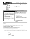
10. Connect circuit wiring to terminal block. (see Fig.2.)
11. Plug detector head into the back box socket.
Secure detector to wall box with screws provided and cover screws with screw caps.
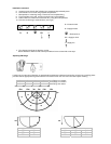
Adjusting PIR Range
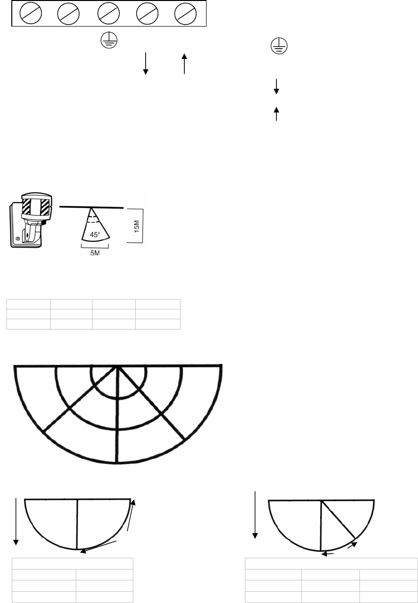
Limit the range and angle of detection as appropriate by adjusting the detector head and by using the lens masking plates
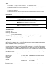
provided. Cut the appropriate segments from the lens mask to cover the area of the lens that requires masking.
A1 A2 A3 A4 Long Range 6-15 metres
B1 B2 B3 B4 Inner Range 3-12 metres
C1 C2 C3 C4 Short Range 0-3 metres
90º 45º 0 45º 90º
Masked Areas Masked Areas
AC A4 A1 A2 A4
B3 B4 B1 B2 B4
C3 C4
C1 C2 C4
N N
S
LI L
N = Neutral to load
N = Supply Neutral
= Earth terminal
SLI = Supply to load
L = Supply live
15m 12m 3m 3m 12m 15m
C1
C2
C3
C4
B4
B1
A4
A1
B2
A2
A3
B3
0
45º
45º
90º
15m
15m
45º
90º