


Model 737 Soundtrack Loudness Meter - Leq(m) Operation and Features
2-3
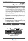
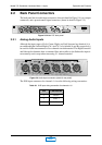
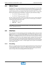
2.2 Back Panel Connectors
The back panel has six audio input connectors (shown in detail in Figure 2-4), two output
connectors, and a power/control signal connector (shown in detail in Figure 2-5).
Figure 2-3
Model 737 back panel
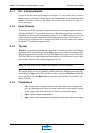
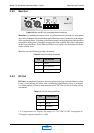
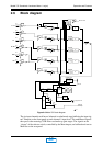
2.2.1 Analog Audio Inputs
Although the input stages of Left, Center, Right, and Left Surround are identical, it is
recommended that Left and Right (Ch 1 and Ch 3, also labeled Lt and Rt, respectively)
be used for Lt/Rt measurements of two-channel encoded material. The Right Surround
and Subwoofer channels share a common filter and rectifier so the Subwoofer input is
not normally used except when measuring 5.1-channel material.
Figure 2-4
Audio input connectors (detail of rear panel)
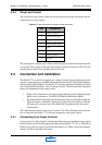
The XLR input connectors for channels 1–6 use the following wiring convention:
Table 2-1
XLR input wiring convention for channels 1-6
Pin Connection
1Chassis
2Audio +
3 Audio -
Ch 1
Lt
Left
Dolby and the double-D symbol are trademarks of Dolby Laboratories.
Ch 3 Rt
Right
Ch 2
Center
Ch 4
Left Surround
Ch 5
Right Surround
Ch 6
Subwoofer
Mon Out DC Out
24Vac
500mA
AC In ~
AC In ~
Ref
Gnd
Trip Out
Trip Out
Trip Out
Gnd
Start / Stop
Analog Audio Inputs
Model 737
Dolby Laboratories Inc.
No user service-
able parts inside.
Refer all service
to qualified
personnel.
WARNING:
San Francisco U.S.A.
Wootton Bassett U.K.
Ch 1
Lt
Left
Dolby and the double-D symbol are trademarks of Dolby Laboratories.
Ch 3 Rt
Right
Ch 2
Center
Ch 4
Left Surround
Ch 5
Right Surround
Ch 6
Subwoofer
Analog Audio Inputs
MAIN