


220V Signature/Series E & V by Draper
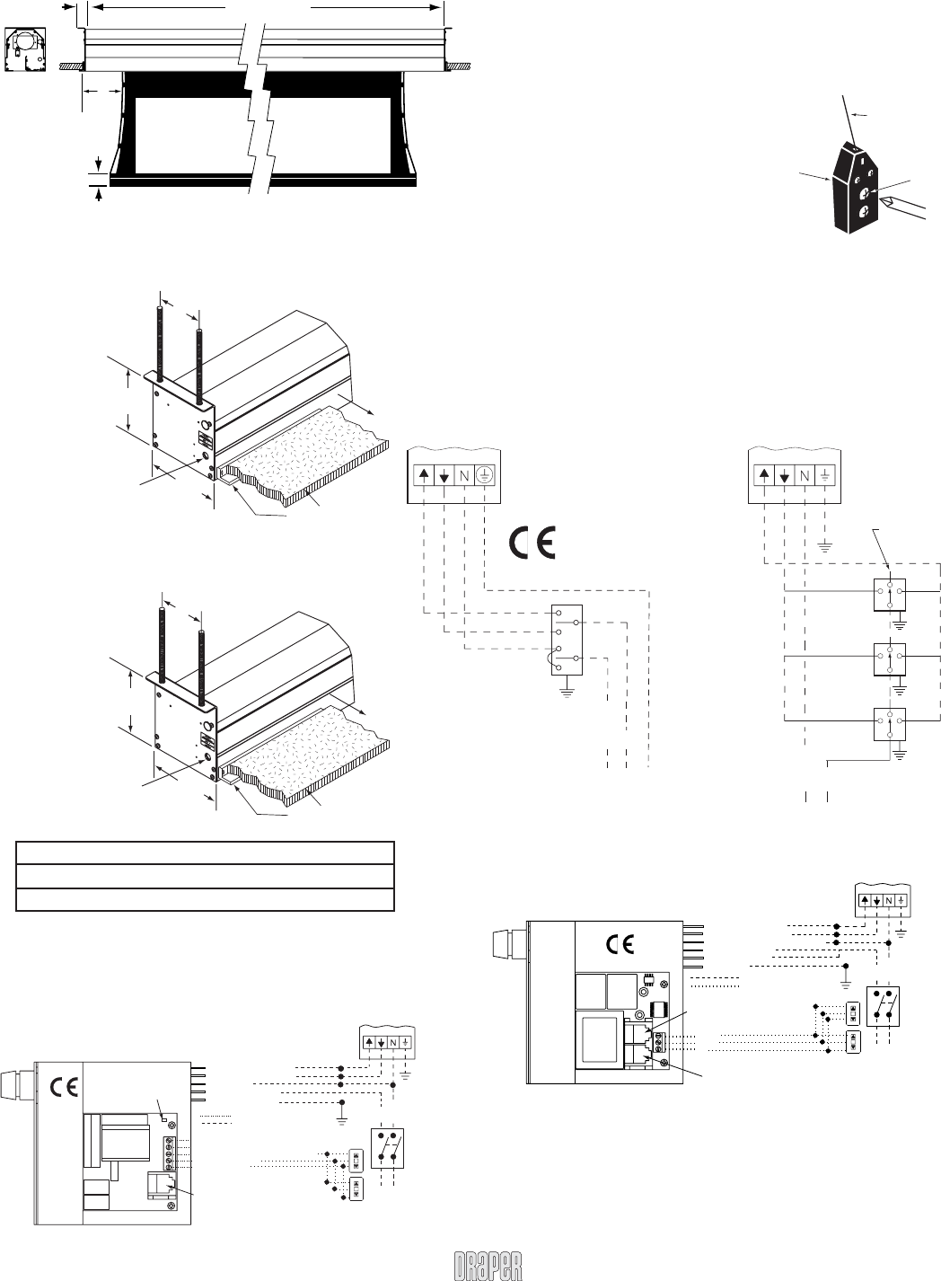
Single Station Control
CE Approved
Terminal strip in
junction box at left
end of screen
Dashed wiring
by electrician
Neutral
L1
230V,
50 Hz.
Terminal strip in
junction box at left
end of screen
Dashed wiring
by electrician
Neutral
Hot
Multiple Station Control
Not CE Approved
Cap off with wire
nut & tape
Red
Red
Red
Blue
Blue
Blue
Black
Black
230V, 50 Hz.
Control
switch
Black
PE
Wiring Diagrams
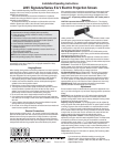
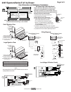
Case Dimensions and Methods of Installation
Page 2 of 2
Dowel
Adjustment
Screw
Tensioning
Cable
Draper’s Tab-Tensioning System is factory-set, and
under normal circumstances will not require fi eld
adjustment. If, however, you notice wrinkles, waves, or
other indications that the tensioning cables need to be
adjusted, follow the procedure below.
➀ Determine which side requires adjustment.
➁ Secure dowel with one hand.
Caution: Do not touch or bend surface.
➂ Using Philips-head screwdriver, depress
spring-loaded adjustment screw (see
Fig. 1) and slowly turn clockwise to tighten
tension, or counterclockwise to loosen tension.
The screw adjusts in ¼ turn increments. Adjust
only one increment (¼ turn).
➃ If problem is not corrected, leave screen in position
for 24 hours to allow surface material to stretch into position.
➄ If problem still is not corrected, repeat steps 2 and 3.
Tab-Tensioning Cable Adjustment
Figure 1
www.draperinc.com
(765) 987-799
9
MC1
See separate Serial Communication-RS232 Instruction sheet for
enabling RS232 with the MC1.
3 Button Wall Switch
DOWN - Black
COM - White
UP - Red
Eye Port for IR Eye, RF Receiver or LED
Switch For more than one of these,
a splitter is required.
Aux Port for connecting additional
LVC-III modules (up to six total-
connect from Aux to Eye).
Red-to screen (directional)
Brown-to screen (directional)
White-Common to screen, 110-120V AC
Black-to 110-120V AC
Yellow-to 110-120V AC
Green-Ground
Dashed wiring by electrician
Low voltage wiring by others
Terminal strip in
junction box at left
end of screen
230V, 50 Hz.
Neutral
Hot
All-Pole Disconnect
by Others
STOP
Control
Switches
24v DC
STOP
RS232 Data FROM Control System
RS232 Data TO Control System
Signal Ground & Manual Switch Common
Manual Switch Down
Manual Switch Up
Red-to Screen (directional)
Black-to Screen (directional)
Blue-Common
Brown-Hot to 230V AC
Green/Yellow-Ground
Fuse
Program LED
Eye Port for IR Eye. For RF Receiver
or LED Wall Switch, a Splitter and a
Power Supply is required. Plug RF
Receiver or LED Wall Switch and
Power Supply into splitter, then run
cable from Splitter to MC1 Eye Port.
Low Voltage Wiring by others
AC Wiring by electrician
MC1
Terminal strip in
junction box at left
end of screen
230V, 50 Hz.
Neutral
Hot
All-Pole Disconnect
by Others
STOP
Control
Switches
24v DC
STOP
Low Voltage & Wireless Control
SCREEN SIZE CASE SIZE
Total Drop < 396 cm or viewing width < 366 cm Small
Total Drop > 396 cm or viewing width > 366 cm Large
NOTE: Viewing surface shown is Series V with tab tensioning.
Series E, without tab tensioning, is also available.
Case length
38 mm Typ
Viewing surface
54 mm
A
Series A
E-small case 81 mm
E-large case 114 mm
V Varies
Ceiling grid
and tile
(by others)
232
cm
152
mm
248
cm
Audience
Electrical connection
to internal splice box
on left end of case. 22mm
knockout for 13 mm
conduit. J-Box cover located
under splice box.
Shown with
9.5 mm
threaded rod
(provided
by others).
Ceiling grid and tile
(by others)
Audience
Electrical connection
to internal splice box
on left end of case. 22mm
knockout for 13 mm
conduit. J-Box cover located
under splice box.
Shown with
11 mm
threaded
rod (provided
by others).
Ceiling grid and tile
(by others)
232
cm
152
mm
280
cm
Small Signature Case
Large Signature Case