


September 2003
CA03310002E For more information visit: www.cutler-hammer.eaton.com
19
NEMA Contactors & Starters
IT. Electro-Mechanical
Dimensions
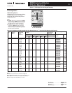
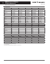
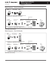
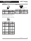
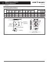
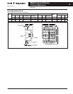
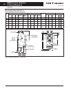
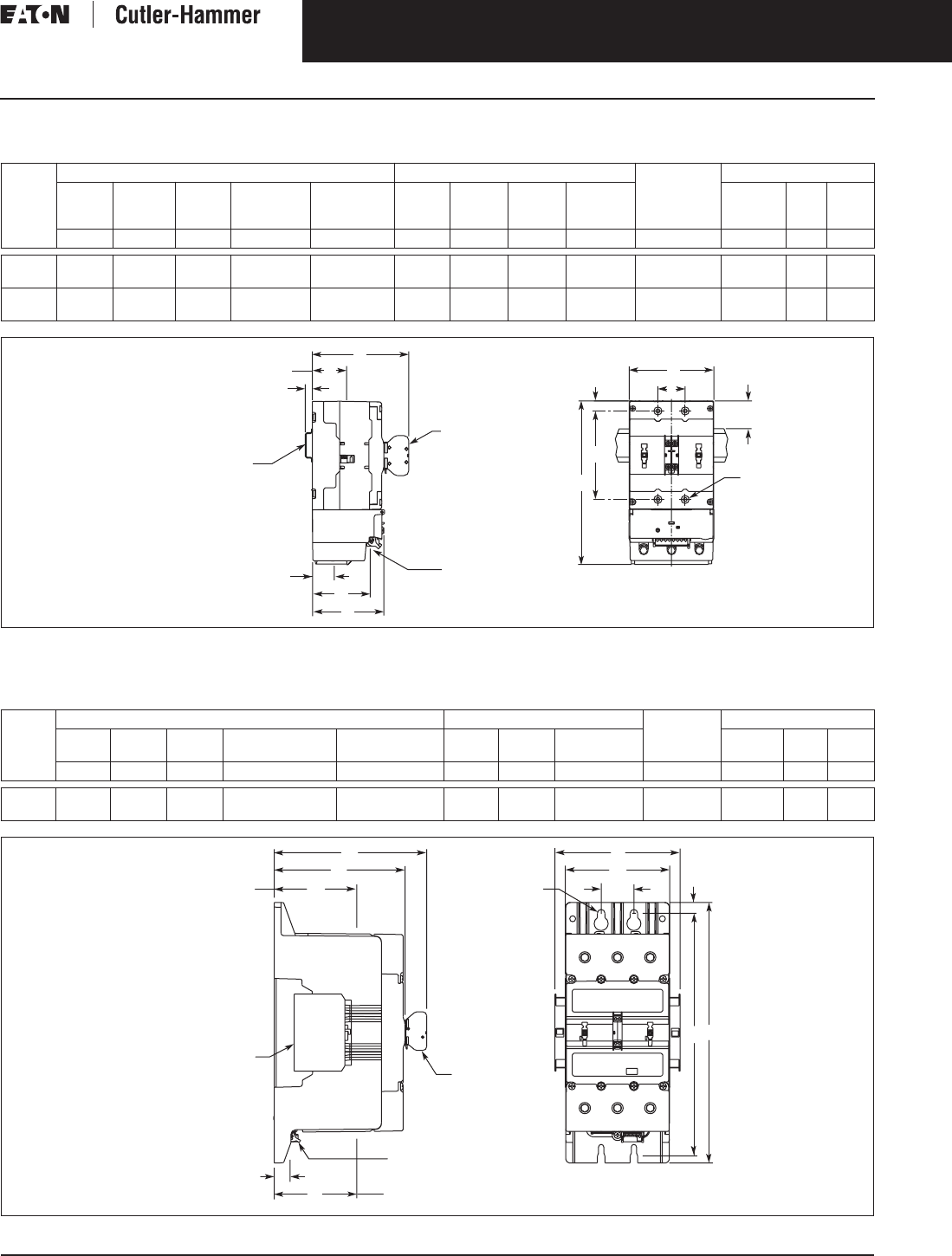
Non-reversing Contactors (Sizes 2 – 4)
Table 24. Approximate Dimensions in Inches (mm)
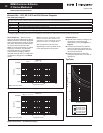
Figure 10. Approximate Dimensions — Inches (mm)
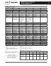
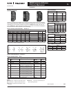
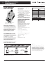
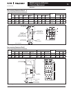
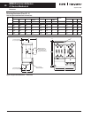
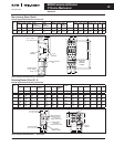
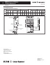
Non-reversing Contactors (Size 5)
Table 25. Approximate Dimensions in Inches (mm)
Figure 11. Approximate Dimensions in Inches (mm)
NEMA
Size
Overall Mounting Holes Req. Mtg.
Screws
Terminals
Width Height Depth Depth w/
Auxiliary
Depth
added w/
DIN Rail
Width Height Mtg.
Hole to
Top
DIN Rail
to Top
Control Line Load
AB CD E FGHJ K P QR
2 3.0
(76)
5.9
(150)
3.1
(79)
4.2
(107)
.2
(4)
.94
(24)
2.87
(73)
.5
(13)
.9
(23)
(4) #6 x 2
M3.5 x 50
2.4
(60)
1.5
(37)
.6
(14)
3, 4 4.1
(105)
8.0
(203)
3.5
(90)
4.7
(119)
— 1.33
(33.8)
4.13
(105)
.6
(15)
— (4) #8 x 1.5
M4 x 40
2.8
(72)
1.7
(42)
.3
(8)
NEMA
Size
Overall Mounting Holes Req. Mtg.
Screws
Terminals
Width Height Depth Depth w/Logic
Level Auxiliary
Width w/Side
Auxiliaries
Width Height Mounting
Hole to Top
Control Line Load
ABCD E FGH K P QR
5 5.6
(142)
14.0
(355)
7.0
(178)
8.2
(208)
6.70
(170)
1.75
(44.5)
13.0
(330)
.58
(14.7)
(4) 5/16
M8
.8
(20)
4.4
(112)
4.4
(112)
2T1
T24
T36
K
J
H
G
B
Dual Auxiliary –
Reduce Dim “D”
.31 (8) for the
Single Auxiliaries
A
F
Q
E
D
Line Terminals
(1 L1, 3 L2, 5 L3)
Standard
DIN Rail
1.38 x .3 (35 x 7.5)
(Optional Mounting)
76 mm (D-Frame) Only
Control
Terminal Block
R
P
Load Terminals
(2 T1, 4 T2, 6 T3)
Size 3, 4 Shown
C
Load Terminals
(2 T1, 4 T2, 6 T3)
P
R
Line Terminals
(1 L1, 3 L2, 5 L3)
D
C
Q
E
A
F
K
Logic
Auxiliary
Side
Auxiliary
Control Terminal
Block
G
B
H