


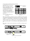
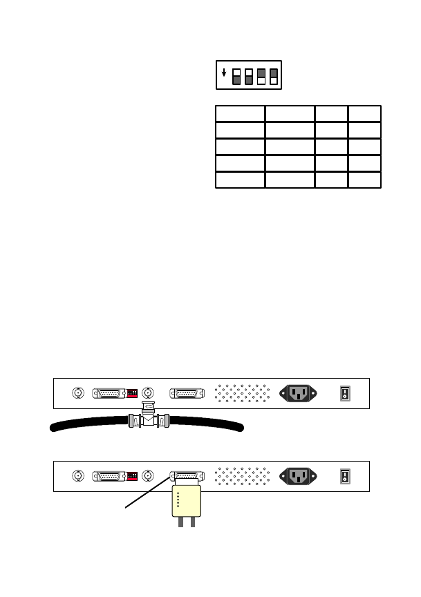
4. Connecting network devices with coaxial cables
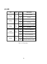
ER-5398S provides two auto-detect
BNC/AUI coaxial ports, each can
function as either BNC or as AUI but
can be used at the same time. A set
of configuration DIP switches are
located between port 1 and port 2,
they can be used to configure the
coaxial port as auto-detect, BNC only
or AUI only as illustrated in Figure 5-2
and Table 5-1.
NOTE : The default setting is auto-
detect mode.
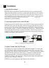
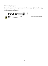
When using the BNC port, attach the T-connector to the BNC port on the rear panel
and connect the coaxial cables to the both open ends of the T-connector as illustrated
in Figure 5-3. If the ER-5398S is at either end of the coaxial segment, make sure
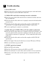
terminate the open end of T-connector with a 50-ohm terminator. When using the
AUI port, firmly attach the AUI transceiver to the AUI port and secure the
transceiver into the socket. The AUI transceiver’s SQE (Heart Beat) should be set
off.
Note : Do not connect coaxial cable directly to the BNC port without using T-
connector.
7
ON
1 2 3 4
Port 1
Auto
AUI
BNC
AUI
Port 2
Auto
BNC
AUI
AUI
1
ON
ON
OFF
OFF
2
ON
OFF
ON
OFF
Figure 5-2 DIP Switch for
AUI/BNC port
Table 5-1 DIP Switch configuration for
AUI/BNC port
1
234
ON
BNC 1BNC 2 AUI 1AUI 2
Power 100-240VAC 1A
Figure 5-3 Connect the coaxial cables
1
234
ON
BNC 1BNC 2 AUI 1AUI 2
Power 100-240VAC 1A
Push to the righthand
side to fix
Figure 5-4 Connect the AUI transceiver