


Eiki A-6 manual Page 7
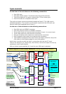
Interfacing to the MultiMedia Port.
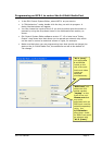
If you wish to control the A-6 internal switchers in some other way, or configure the
unit as a standalone, fixed input wallplate, you will need to know the control port
connector pinouts for the ribbon cable. They are as follows:
Pin Function Type Comment
1 Relay output Logic Low RL1
2 Relay output Logic Low RL2 (not implemented on MCS-1)
3 GP output 2 Not used
4 RGBHV source Logic Low input Low = Front PC input
5 AV source 1 Logic Low input See table below
6 AV source 2 Logic Low input See table below
7 RGBHV sense Logic output
8 Video sense Logic output
9 GND
10 +24 v Power Any positive voltage from 9v to
30v. DC.
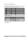
AV switcher truth table
Input Pin 5 Pin 6 Comments
AV in 1 (rear) H H Audio 1 is mono. Video 1. On rear
AV in 2 (rear) L H Audio and video 2 on rear
Video & Audio 3
(front)
H L Audio shared with front PC socket
Front video input
A in PC (rear) L L Audio from rear PC socket
Video 4 input rear
“H” = not connected.
“L” = connected to pin 9