ongratulations on your purchase of the AP-3000 Avionics
C
Panel. This guide is an addendum to the ELITE Hardware
Installation Manual and will provide the necessary information
for proper setup of the AP-3000.
IMPORTANT
The AP-3000 comes with its own special Power Supply. Using a
different power supply will cause unpredictable results and may
damage the AP-3000.
! The AP-3000 Power Supply should only be used to power
the AP-3000 by itself. Do NOT use AP-3000 Power Supply
to power other components.
! Connect AP-3000 as shown in the diagrams on the opposite
page or in the ELITE Hardware Installation Manual.
! Refer to the ELITE Hardware Installation Manual for
information on connecting other system components as
applicable.
NOTE:
The AP-3000 is designed to be similar in operation and function
to common avionics stacks found in actual aircraft. With few
exceptions, its use should be intuitive and integrate easily with
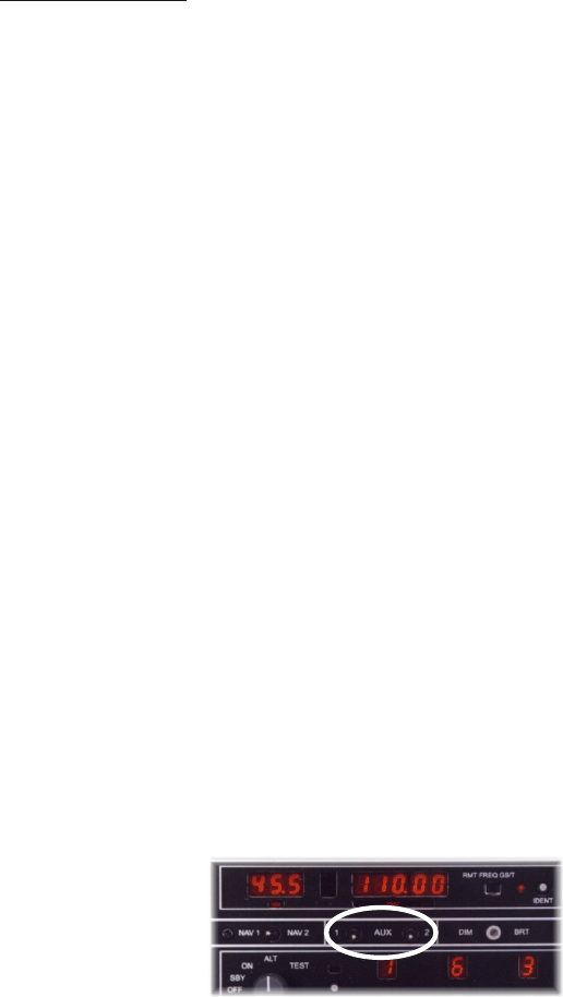
any system. A few functions unique to the AP-3000 are the
AUX 1 & AUX 2 toggle switches (pictured below). AUX 1 is an
ON/OFF style switch that controls the display of the on-screen
Moving Map. AUX 2 is used for DME selection in the King Air.
AUX 1 & 2 toggle switches
Connecting the AP-3000
Flight Console
(back view)
Rudder
Avionics
UCI
flight console
(
25 pin - 9 pin cable
)
Power
AP-3000
(back view)
Avionics
(
9 pin - 9 pin cable
)
Throttle
Quadrant
(back view)
AP-3000
(back view)
Extended
Standard
Avionics
(
9 pin - 9 pin cable
)
quadrant
(
25 pin - 25 pin cable
)
NOTE
External power connections
not shown.
Systems with a
Flight Console
Systems with
Separate Quadrant
Serial
Port
IOIOIO
Serial
Port
IOIOIO


