


A.6.4 Auxiliary Feedback Port (input mode YA[4]= 2, 0)
Feature Details
Encoder input,
pulse and direction input
A, B, Index
Single ended
Input voltage V
In
Low: 0 V < V
IL
< 0.8 V
V
In
High: 2 V < V
IH
< 5 V
Maximum absolute voltage: 0 < V
In
< 5.5 V
Input current: ±1 µA
Available as options
Single-ended Encoder inputs
Pulse and Direction inputs
Edge separation between A & B
Programmable number of clocks to allow adequate
noise filtering at remote receiver of emulated
encoder signals
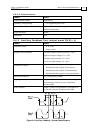
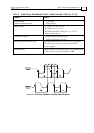
Index (marker): Length of pulse is one quadrature (one quarter of an
encoder cycle) and synchronized to A&B
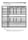
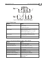
Figure A-3: Auxiliary Feedback - Encoder Phase Diagram
Guitar Installation Guide Guitar Technical Specifications
MAN-GUIIG (Ver. 1.1)
A-11